Content last revised on October 16, 2026
Aluminum Heat Spreader Sizing and Thermal Interface Placement Along Narrow Display Edges
Thermal assessment around a narrow display edge should start at the actual heat sources rather than at the panel glass. Inspect the enclosure airflow, controller proximity, backlight driver position, and any metal frame that can conduct heat into one side of the module. An aluminum spreader rail can be considered where a localized warm region develops, but its contact area, electrical isolation, pressure distribution, and clearance from the display must be determined by the complete mechanical assembly.
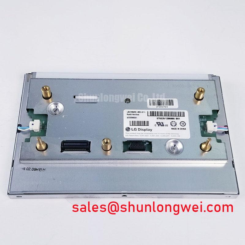
This is a Design Consideration, not a confirmed LB070WV3-SD02 construction detail. Do not introduce a rail that presses against the active area, distorts the bezel, or transfers chassis vibration into the panel. A thin, even thermal interface may be evaluated where the enclosure design requires heat transfer, while the system engineer verifies temperature uniformity during extended operation.
For bright factory floors, sunlight readability depends on the combined effect of panel contrast, surface reflection, ambient illumination, viewing direction, and any anti-glare or anti-reflective treatment. The supplied baseline does not confirm a contrast ratio above 500:1 at 50,000 lux, nor does it confirm an AG coating for this model. Treat those values as acceptance-test criteria only when they appear in the original panel documentation. General TFT-LCD operating principles are described in the TFT-LCD technology reference, while industrial display construction examples can be reviewed through Winstar industrial TFT-LCD modules.
Radiated Emissions Investigation Through Backplate Grounding and Cable Control
Pixel jitter and horizontal noise bands near variable-frequency motor drives should be investigated as a complete signal-integrity problem. Check cable routing relative to motor output conductors, verify connector retention, inspect the shield termination at both the display and controller ends, and compare the disturbed image with the drive disabled. A shielded FFC or LVDS cable may require a controlled chassis termination, but the exact grounding topology remains system-dependent.
Multi-point or star-style backplate grounding can be evaluated as a Design Consideration when the enclosure produces common-mode noise. The intended result is a low-impedance return path for shield currents without allowing high-current motor transients to share the display signal reference. Ferrite suppression may also be assessed at the cable entry when conducted or radiated interference is demonstrated during testing. These measures do not establish independent CISPR Class A or Class B compliance for the display module; EMC performance belongs to the assembled equipment and its verified installation.
Backlight troubleshooting should separate an image-path fault from an illumination fault. If the controller produces valid image data but the screen remains dark, inspect the backlight driver output, connector continuity, open-load response, short-load response, and fault indication. The supplied LB070WV3-SD02 baseline does not specify LED string voltage, current, protection thresholds, or an MTBF curve. Do not apply a constant-current driver until the required backlight electrical data has been confirmed from the original documentation.
Viewing Direction Alignment and Grayscale Inversion Assessment
Operator position is especially important when a replacement panel is installed in a fixed machine console. A TN display can show tonal inversion when viewed away from its preferred axis, so assess the actual seated and standing positions rather than judging the panel from directly in front. Align the display surface with the normal operator sightline, then inspect grayscale ramps, alarm colors, fine text, and dark-background graphics from the permitted working positions.
The supplied baseline does not confirm that this model uses a normally white TN cell, an IPS or MVA structure, a symmetric 85°/85°/85°/85° viewing cone, or a particular AG etching treatment. Those descriptions must not be assigned to the LB070WV3-SD02 without a matching technical document. They are useful comparison criteria when reviewing a candidate replacement, especially where machine alarms depend on stable grayscale interpretation.
| Evaluation point | LB070WV3-SD02 | Alternative review reference |
|---|---|---|
| Manufacturer | LG Display | Confirm from the original documentation |
| Module category | TFT-LCD active matrix color display | Compare construction and interface requirements |
| Mechanical role | Industrial LCD/HMI panel, standard form factor | Check outline, mounting points, and connector location |
| Replacement candidate | LB070WV3-SD02 | LQ64D343, subject to full compatibility verification |
The LQ64D343 should therefore be treated as a separate engineering evaluation, not an automatic substitute. Compare active area, resolution, interface signaling, timing, backlight arrangement, mounting envelope, and optical direction before any cross-model decision. If the operator relies on gloves, moisture, or a resistive or capacitive touch overlay, confirm the touch assembly separately; the supplied baseline identifies the LCD module but does not confirm an integrated touch sensor.
Flush-Mount Open-Frame Bezel Integration and Perimeter Gasket Shock Isolation
Flush mounting begins with a mechanical drawing, not with fastener tightening. Check the chassis cutout, bezel overlap, connector clearance, cable bend path, gasket compression, and the possibility of frame contact against the active display area. A perimeter gasket can help isolate vibration and prevent direct metal-to-glass contact, but its thickness, hardness, and compression must be selected for the complete enclosure.
Cross-pattern tightening is a reasonable Design Consideration for distributing frame pressure, while the permissible fastener torque must come from the panel or chassis assembly specification. The supplied baseline does not confirm an M3 torque limit of 0.35–0.45 N·m for this model. Excessive or uneven loading may produce localized optical non-uniformity, but the repair engineer should verify this by loosening the frame in a controlled sequence and observing whether the dark-field pattern changes.
For a machine-tool HMI, route the display cable so that it is not trapped between the bezel and enclosure, and keep the connector latch fully engaged before closing the panel. ⚠️ Field Alert: Disconnect system power before inserting or removing the display cable to reduce the risk of signal-pin disturbance.
Backlight behavior should be checked after mechanical installation, because a pinched cable or displaced gasket can create an intermittent fault that appears only after vibration or thermal cycling. A separate LG Display solution such as LQ084S3LG03 may be reviewed when the equipment architecture calls for a different display size or topology. For enclosure, grounding, and harsh-environment integration principles, consult the Industrial Display and HMI Solutions engineering guide.