


Content last revised on September 10, 2026
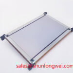
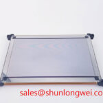
LJ640U32 Sharp Industrial Grade LCD HMI Panel
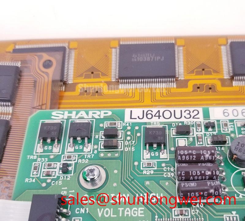
Begin incoming inspection by checking the LJ640U32 display module against the purchase record, examining the TFT-LCD housing for transport damage, and confirming the manufacturer marking before applying power. This procedure establishes a clean baseline without assuming electrical or optical values that are not listed in the available factory specification.
| Item | Verified Information |
|---|---|
| Model | LJ640U32 |
| Manufacturer | Sharp |
| Product category | Industrial Grade LCD/HMI Panel |
| Construction | TFT-LCD Display Module |
| Specification status | Detailed factory specifications require confirmation from the applicable model documentation |
The available product data identifies this unit as a Sharp TFT-LCD display module for industrial HMI and monitoring equipment. Detailed values for active area, pixel resolution, luminance, viewing angle, interface type, supply voltage, backlight construction, connector pinout, and environmental limits should be confirmed from the original panel documentation before a replacement is energized. The system integrator should verify the required supply voltage and signal format from the equipment service documentation rather than transferring assumptions from another Sharp panel.
Preventing Localized Light Guide Plate Compression Warp on Dark Screen Fields
Dark-field inspection is useful because mechanical pressure can appear as localized brightness variation even when the display produces a correct image. Install the panel in a clean, supported chassis and inspect the bezel contact pattern before tightening every fastener. The mounting frame should distribute load evenly around the display perimeter, while the inner opening should provide sufficient clearance to prevent the bezel from pressing into the visible display area.
The supplied information does not confirm a factory mounting torque, chassis tolerance, or internal optical construction for this model. Any proposed fastener torque must therefore be treated as a Design Consideration, not as a Sharp specification. When engineers evaluate a replacement in a Zone 2 petrochemical operator station, they should compare the original frame geometry, gasket compression, screw position, and panel seating method. The enclosure must also preserve the equipment’s certified protection concept; the LCD module itself should not be treated as independently certified for hazardous-area operation.
Run a uniform dark image after mechanical installation and inspect the screen from the normal operator position. A broad shadow that changes after loosening the frame can justify a mechanical review, while a fixed patch should be compared with an unmounted test image before assigning a cause. For cold environments, the display response may become visibly slower as liquid crystal viscosity increases. A heater strip or enclosure temperature-control system may be considered only after its heat distribution, control logic, and power interaction have been evaluated by the system designer.
Bench Tip: Use ESD protection and keep the display flex connector perfectly parallel to the socket before locking it; angled insertion can create intermittent signal faults that resemble panel damage.
Suppressing Localized Thermal Gradients to Prevent Chronic Optical Yellowing
Thermal inspection should focus on temperature differences across the narrow display edges rather than on average enclosure temperature alone. Record the condition of the bezel, backlight region, nearby power components, and cable entry points while the equipment operates at its normal image load. A local hot spot may arise from the surrounding assembly, airflow restriction, backlight driver, or an adjacent power stage, so the LCD should be assessed as part of the complete HMI assembly.
The available factory information does not specify an L70 or B50 lifetime rating, LED junction temperature, optical material composition, heat spreader dimensions, or allowable temperature gradient for LJ640U32. These values must not be inferred from the Sharp brand or from a visually similar panel. An aluminum spreader rail can be evaluated as a Design Consideration where it improves heat distribution, but its dimensions, electrical isolation, grounding, and contact pressure remain system-level decisions.
Signal integrity requires the same discipline. If the host system uses LVDS or TTL signalling, the integrator should verify the actual interface from the original documentation, including differential polarity, connector assignment, clock relationship, termination, and power sequencing. A generic impedance target or skew limit should not be presented as a factory parameter for this model. During commissioning, probe the known-good signal path with suitable high-bandwidth instrumentation and compare the replacement panel under identical cable routing and image conditions.
For background information on industrial display optics and panel selection, engineers can consult the The Ultimate Guide to Industrial TFT-LCD Technology. Sharp’s official display solutions portal is also a useful reference point for manufacturer-level product context, although the exact electrical limits for this panel still require the applicable model documentation.
Wide Temperature Operational Margin and Sub-Zero Liquid Crystal Viscosity
The requested evaluation range of −30°C to +85°C should be treated as a system qualification condition, not as a confirmed operating rating for LJ640U32. The available factory parameter set does not provide a verified operating temperature range, storage range, cold-start requirement, seal qualification, or response-time curve. Engineers considering this module for an outdoor monitoring cabinet or a petrochemical operator station should obtain the original environmental specification before approving the installation.
At low temperature, image transitions can become slower and grey-level changes may show visible trailing. This observation is a general LCD design consideration rather than a model-specific guarantee. A controlled cold-start test should monitor supply behavior, image initialization, contrast, uniformity, and transition performance while the complete panel assembly reaches the target temperature. If a heater is used, its controller should be assessed for overshoot, local heating, condensation risk, and interaction with the enclosure’s hazardous-area protection method.
At elevated temperature, verify the panel surroundings rather than relying only on the air temperature measured inside the cabinet. Cable bundles, LED driver boards, sun loading, and sealed enclosure airflow can produce local conditions different from the ambient sensor location. The mechanical frame should allow thermal expansion without adding uneven pressure to the display. Any perimeter seal or gasket used by the equipment manufacturer should be evaluated for compatibility and long-term compression behavior through the complete qualification program.
When the display is integrated into a variable-frequency drive control cabinet, image stability should be evaluated alongside conducted and radiated interference from the inverter, motor cable, and switching power supply. The VFD system reference provides general background on the switching environment, but it does not define the immunity of this Sharp display. Cable shielding, bonding, routing, and filter selection should be validated on the finished equipment.
Full-Screen Primary Color AOI Screening: Stuck Sub-Pixels and Background Uniformity Audit
Perform the optical audit with full-screen red, green, blue, white, black, and neutral test fields generated by a known-good controller. Observe the display at a consistent distance and viewing angle, then record any fixed bright point, dark point, color deviation, line defect, flicker, or uneven background. The inspection should be performed before and after mechanical installation so that image defects can be separated from enclosure-induced optical variation.
A 45-degree flashlight inspection can help identify whether a dark region is associated with surface contamination, an external shadow, or a deeper display-line anomaly. Keep the light intensity and inspection angle consistent, and avoid pressing the front surface during examination. A suspected COG or trace-related defect should be compared with the same image pattern after cable reseating and controller substitution where available. This is a comparative diagnostic method, not a universal pass or fail threshold for LJ640U32.
Check the connector and cable in stages: inspect contact alignment, confirm full insertion, secure the locking mechanism, and repeat the color-field test while gently observing the cable path without applying force to the panel. If the system uses high-speed differential signalling, an oscilloscope comparison with the known-good signal path may reveal ringing, discontinuity, or impedance mismatch. The exact differential impedance, skew budget, clock rate, and timing margins must come from the interface specification of the original equipment.
For replacement planning, engineers may also evaluate LM057QC1T08 as a separately documented display option, but dimensional, optical, connector, and firmware compatibility must be checked independently rather than assumed. In a broader display assembly, LQ150X1LG11 may be reviewed as a complementary display solution, subject to its own documentation and system interface requirements.
Record the incoming condition, controller used, test pattern, ambient condition, mounting state, and observed defect location in the service file. This creates a repeatable comparison for procurement and repair teams without assigning an unsupported field failure rate or operating-life estimate to the Sharp LJ640U32.