Content last revised on September 10, 2026
SKM300GA12V Product Identity and System Context
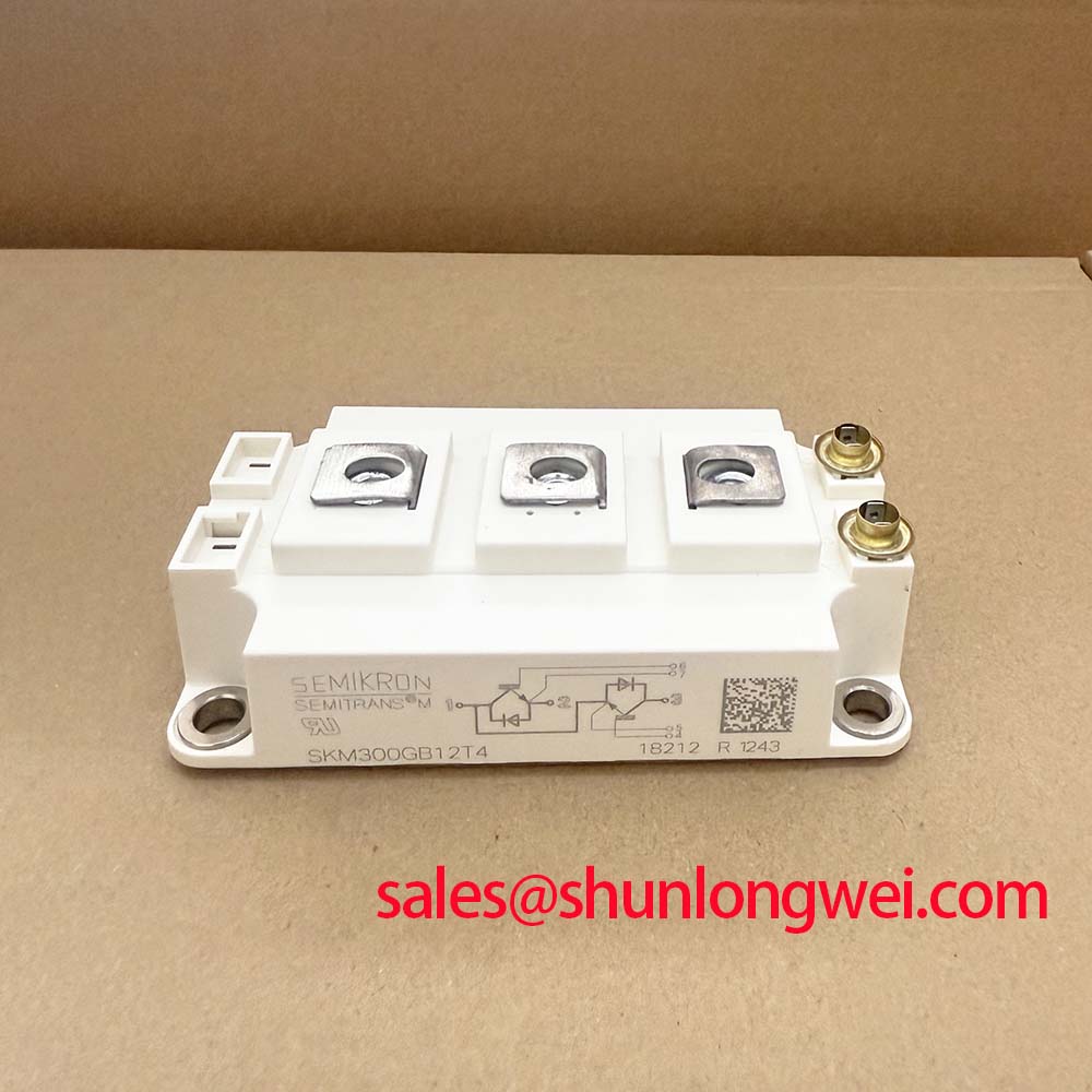
Before installation, verify that the equipment bill of materials and module marking identify SKM300GA12V, then isolate the DC link and compare the intended voltage and current boundaries with the official ratings. This Semikron IGBT module is specified at 1200 V collector-emitter voltage and 300 A rated collector current under the specified conditions in the SEMITRANS housing platform.
| Parameter | Official Specification |
|---|---|
| Product model | SKM300GA12V |
| Manufacturer | Semikron |
| Collector-emitter voltage | 1200 V |
| Rated collector current | 300 A under specified conditions |
| Housing platform | SEMITRANS |
The module should be assessed as part of its complete converter, including DC-link capacitors, busbar geometry, gate-driver isolation, cooling path, and protection response. Semikron Danfoss identifies SEMITRANS as an industry-standard power-module platform; engineers can review the related SEMITRANS industry-standard IGBT information when checking package-level integration expectations.
Preventing Spurious Faults: Regenerative DC Bus Voltage Surge Dissipation Guidelines for SKM300GA12V
During motor deceleration, stored mechanical energy can return through the inverter to the DC bus. Before attributing an overvoltage trip to the SKM300GA12V, measure the DC bus at the capacitor terminals and compare the event timing with the braking command, motor speed reduction, and protective shutdown sequence. A rising bus voltage may indicate that the braking path, energy storage capacity, or control logic needs system-level review.
Design Consideration: where a converter uses an internal or external braking switch and ballast resistor, their pulse-energy capability, thermal path, cable routing, and controller threshold must be evaluated together. The braking branch should not be dimensioned from IGBT current rating alone. The system engineer should calculate the recoverable kinetic energy, expected duty cycle, and allowable DC-link operating window, then validate the result with instrumented deceleration tests.
Keep the braking loop and DC-link connection physically compact to reduce inductive overshoot when the energy path commutates. Clearance and creepage requirements must follow the complete equipment insulation design, working voltage, pollution environment, and applicable installation standard. For inverter welders or medium-frequency induction heating power supplies, a disturbance seen as an intermittent gate-driver fault can also originate in the control supply or sensing reference during bus transients.
When a lower-current module is being evaluated for a separate repair design, SKM100GB063D can be reviewed as a distinct Semikron module. Its electrical ratings, terminal arrangement, thermal interface, gate-drive requirements, and system protection coordination must be verified independently; it is not a universal replacement for SKM300GA12V.
Benchtop Waveform Tuning: Mitigating Stress from Potential 2× DC-Bus Voltage at SKM300GA12V Terminals
Probe the module terminals and the DC-link capacitor connection during switching tests before changing gate resistance or adding suppression parts. Long motor leads can behave as transmission paths, and impedance mismatch may produce reflected voltage that approaches twice the DC-bus level at a remote terminal under some switching conditions. This is a system phenomenon, not an official voltage capability of the 1200 V SKM300GA12V.
Engineering Recommendation: minimize the commutation-loop inductance with close-coupled, symmetrical DC-bus conductors and place the DC-link capacitance so the switching current path remains short. Where cable length and reflected-wave behavior warrant it, the system designer should assess output reactors or dv/dt filtering based on measured motor-terminal waveforms, insulation limits, switching frequency, and thermal loading. Verify peak voltage margins against the DC-link voltage during double-pulse and loaded switching tests.
Parallel module arrangements require separate static and dynamic checks. IGBT conduction behavior can support static current sharing through the positive temperature coefficient of VCE(sat) in relevant operating regions, yet matching is not assured by that characteristic alone. Equalized busbar paths, comparable gate loops, synchronized drive timing, and matched cooling conditions remain necessary design considerations. Gate-loop layout should limit shared emitter and collector inductance so Miller-related current does not create unwanted gate excursions during fast commutation.
💡 Pro Tip: Use a symmetrical laminated or closely coupled bus arrangement and confirm turn-off overshoot with a correctly referenced differential probe before accepting any gate-drive adjustment.
In systems with a rectifier or auxiliary power stage ahead of the inverter bridge, the SKM75GAL063D may be reviewed as a separate complementary power-device option. Its suitability depends on the actual topology and verified electrical conditions.
Preventing Spurious Faults: Thermal Interface Material Thickness Uniformity Guidelines for SKM300GA12V
Remove the module only after the DC bus has been discharged and verified safe, then inspect the heatsink contact plane for residue, raised damage, corrosion, or uneven clamping marks. The SEMITRANS baseplate must transfer heat through a controlled thermal interface; localized voids or excessive compound can increase thermal resistance and create unequal junction stress between switching positions.
Design Consideration: apply a thin, continuous thermal interface material layer according to the selected material supplier instructions and the condition of the mating surfaces. Apply only enough material to fill surface irregularities. If baseplate flatness, heatsink flatness, or old compound condition is uncertain, inspect those conditions before attributing elevated temperature to the IGBT module.
Tighten mounting hardware progressively in a balanced sequence so clamping pressure develops evenly across the module. The correct torque, screw type, washer arrangement, and tightening pattern should be taken from the module mechanical documentation and the equipment assembly specification. After recommissioning, compare heatsink temperature distribution and load behavior with a known stable operating condition where available.
Field Diagnostics & Commissioning: Reinforced Isolation Barrier Integrity in SKM300GA12V Topologies
During commissioning, confirm that gate-drive isolation, current sensing, control power, and measurement equipment preserve the intended galvanic separation between the power bridge and low-voltage controls. Do not assume a reinforced isolation voltage rating or common-mode transient immunity value for the complete drive chain from the IGBT module designation. Those properties belong to the selected driver, isolated supply, PCB spacing, connectors, and complete equipment construction.
A nuisance turn-on during the opposite switch transition may indicate excessive common-mode coupling, gate-loop inductance, poor driver reference control, or an unsuitable protection sequence. Check the gate-emitter waveform, collector-emitter waveform, desaturation or overcurrent signal, and controller fault record together. Oscilloscope measurements should use suitable high-voltage differential methods and be compared with the known-good signal path wherever possible.
For technical context on switching topologies and resonant operating behavior, see Resonant Topologies in Home Appliances. General product and power-semiconductor reference material is also available through the Semikron-Danfoss official power electronics hub.