Content last revised on October 29, 2026
2MBI200P-140 Maintenance Checks and Specifications
- Isolate the supply, verify that the DC link is discharged, and disconnect parallel circuit paths before checking main-terminal conduction.
- Match the installed module marking, terminal arrangement, and mounting interface to the equipment drawing before removing busbars.
- Inspect the heatsink contact surface, cooling passages, and thermal interface for contamination, uneven contact, or deterioration.
- Check the gate-driver return path and isolation boundary before connecting oscilloscope probes or restoring auxiliary power.
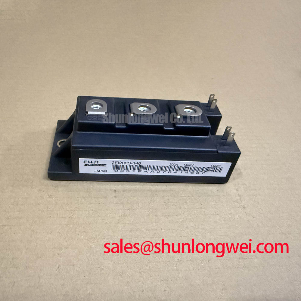
The 2MBI200P-140 is a Fuji Electric IGBT module with the specifications listed below. For maintenance planning, these ratings establish the product identity; operating conditions, mounting requirements, and protection settings remain tied to the equipment design.
| Parameter | Value | Specification identity |
|---|---|---|
| Manufacturer | Fuji Electric | Official Specification |
| Model | 2MBI200P-140 | Official Specification |
| Rated voltage | 1400 V | Official Specification |
| Rated current | 200 A, subject to datasheet conditions | Official Specification |
| Package / case | Fuji Power Module | Official Specification |
| Terminal map, electrical test conditions, dimensions, and mounting limits | Consult Datasheet | Required integration details |
Preventing Spurious Faults: Oscilloscope Waveform Verification for 2MBI200P-140
Compare gate-emitter and collector-emitter waveforms at the module connections when checking unexplained trips after a power-stage repair. Engineering Recommendation: use appropriately rated differential or isolated measurement equipment, with probe connections arranged to limit pickup. Capture switching transitions alongside the driver command so that interference on the measurement lead is distinguishable from an actual gate disturbance.
Design Consideration: external turn-on and turn-off gate resistors influence switching speed, dissipation, and ringing. When a legacy driver is being adapted, evaluate each transition separately under controlled conditions. Increasing resistance can reduce switching aggressiveness while increasing switching losses; reducing it can expose overshoot or recovery-related oscillation. The acceptable balance follows measured waveforms and the equipment thermal budget, rather than a universal resistor value.
Trace the gate return against the terminal drawing. Where an auxiliary emitter connection is explicitly identified, preserve its intended separation from the power-current return. Shared return inductance can alter the effective gate voltage during current transitions. Keep the gate loop compact and away from switching conductors while preserving the equipment’s required clearances.
The Miller plateau concerns gate charge transferred during the collector-voltage transition; reverse-transfer capacitance, commonly designated Cres, is a capacitance rather than a charge quantity. Evaluate off-state gate excursions and any active-clamp response against the actual driver architecture. For comparison work, 1MBI200N-120 provides a related product reference, but interchangeability requires an independent check of ratings, circuit configuration, terminals, and mounting.
Transient Dynamics & Electrical Design: Type-2 Coordination and Protection for 2MBI200P-140
Compare the semiconductor fuse’s total clearing I²t at the applicable circuit conditions with documented protection limits for the complete power stage. Design Consideration: fuse selection also depends on circuit voltage, prospective fault current, interrupting capability, and DC-link discharge behavior. I²t alone does not establish whether an IGBT survives a short circuit or whether its enclosure remains intact.
Type-2 coordination should be treated as an equipment-level classification within its applicable standard and tested assembly. It does not establish a short-circuit withstand rating for the 2MBI200P-140. Engineering Recommendation: review fast driver fault detection, controlled shutdown, and upstream interruption as coordinated functions, including the energy remaining in the DC-link capacitors after the supply is interrupted.
Inspect diode recovery at commutation by observing current reversal and the accompanying voltage waveform. Abrupt recovery can excite parasitic inductance and capacitance, producing ringing that contributes to conducted and radiated interference. A snubber can damp this response, but its placement, dissipation, and component stresses require circuit-specific evaluation. Neither snubber installation nor module selection establishes equipment EMC compliance.
For a compatibility assessment involving a heavy-duty variable frequency AC motor drive, distinguish the motor inverter from its regenerative braking path: a braking chopper switches recovered DC-link energy into a braking resistor. Fuji Electric Brake Chopper IGBT Modules provides manufacturer context for that function without establishing this model as a dedicated chopper. The 1MBI200SA-120B-52 is another IGBT reference for power-stage and driver comparisons, rather than evidence of an interchangeable rectifier function.
2MBI200P-140 Thermal-Electrical Optimization: Reinforced Insulation Barrier Integrity and Practical Tuning
Inspect the driver isolation boundary for contamination, damaged insulation, and routing changes before investigating common-mode gate disturbances. Design Consideration: reinforced insulation is a documented classification of an insulation system, while common-mode transient immunity describes the isolation component’s response to rapidly changing common-mode voltage. Neither property follows from the module’s 1400 V rating.
Engineering Recommendation: assess the driver isolator, isolated supply, connector spacing, and board clearances against the equipment’s working voltage and environmental requirements. Observe the gate signal during collector-voltage transitions to determine whether a disturbance crosses the isolation boundary or develops within the local gate loop. Any insulation test should follow the equipment procedure, with sensitive connected electronics handled as that procedure specifies.
Cooling inspection should connect electrical loading to the actual heat-removal path. Check blocked fins, fan condition, heatsink seating, and thermal-interface coverage. Establish inspection intervals from operating conditions and recorded temperature trends, with attention to condensation after shutdown or movement between environments. The packaging discussion in Beyond the Silicon offers background for reviewing thermal paths and maintenance observations.
Maintenance Note: Monitor terminal temperature trends and verify cooling airflow during scheduled inspections before returning a repaired power stage to sustained service.
Where the equipment uses a temperature sensor, identify its location and transfer characteristic before interpreting the reading. The operating principle described in Negative Temperature Coefficient (NTC) Thermistor explains NTC behavior; it does not establish that this module contains an NTC sensor or that a sensor reading equals junction temperature.
2MBI200P-140 Circuit Protection & Reliability: Pre-Installation Junction Health Check
Use the terminal diagram to identify each accessible semiconductor path before applying a digital multimeter’s diode-check function. Engineering Recommendation: test the isolated module with a meter suitable for semiconductor screening, controlling gate charge through the approved handling procedure. Record lead polarity, terminal pair, temperature, and reading so comparisons remain meaningful.
Check forward and reverse behavior across each documented antiparallel diode path, then inspect gate-emitter and gate-collector behavior for unexpected low impedance. A repeatable difference between comparable paths warrants further investigation, but it does not identify a unique failure mechanism. Connected snubbers, resistors, and driver circuitry can change readings, which is why isolation from external paths matters.
A handheld meter provides preliminary screening; it cannot establish high-voltage blocking performance, quantify low gate leakage reliably, or verify switching behavior under load. Escalate suspicious results to controlled testing with suitable instrumentation. Record the findings against the equipment service procedure, then complete mounting-interface and connection checks before the prescribed staged energization.