


Content last revised on October 13, 2026
SKM200GAL123D Product Identity and Incoming Inspection
With the DC link discharged and verified safe, identify the collector, emitter, and gate connections on the terminal drawing before placing meter probes on the SKM200GAL123D. Record diode-mode readings with the probe polarity, module temperature, and gate condition noted; an isolated reading without those conditions is a poor incoming-inspection baseline. Keep the module disconnected from the driver and buswork so parallel circuitry does not obscure the measurement.
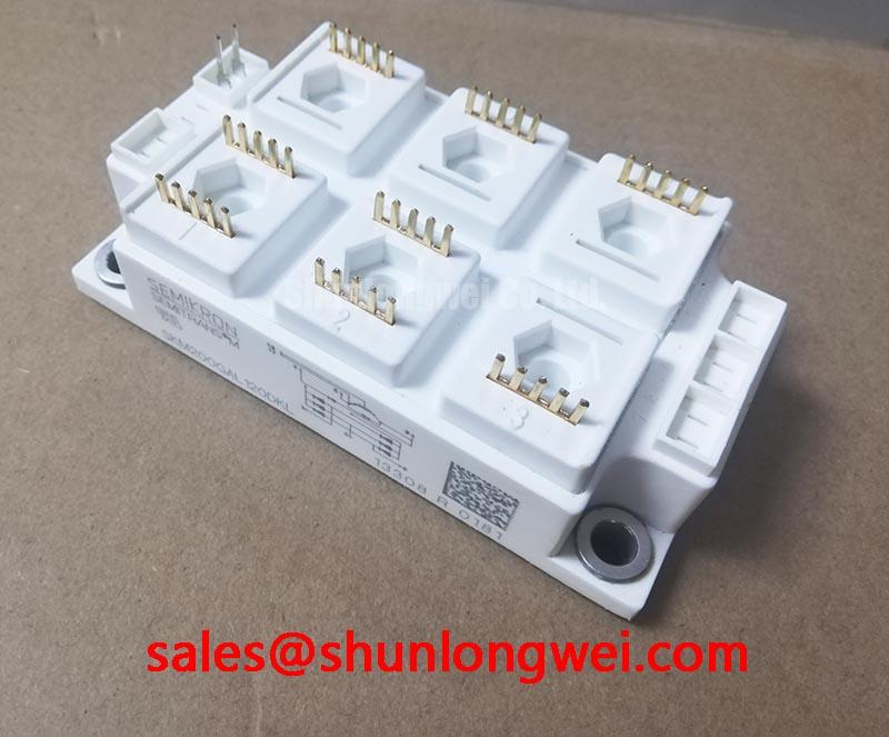
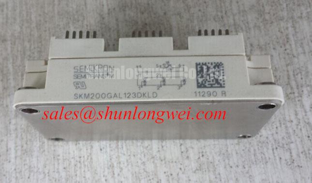
The Semikron SKM200GAL123D is an IGBT module with a 1200 V voltage rating, 200 A current rating, and SEMITRANS package designation. Incoming acceptance should also establish terminal correspondence, mounting compatibility, and the electrical test conditions associated with the original module documentation.
SKM200GAL123D Operational Boundaries: Galvanic Gate-Drive Isolation and Insulation Limits
Trace the isolation boundary through the gate-driver circuit rather than treating the module’s collector-emitter voltage rating as a gate-drive insulation specification. As a Design Consideration, the driver barrier, isolated power supply, PCB spacing, connectors, and enclosure arrangement must collectively support the equipment’s insulation requirements. Neither reinforced insulation nor common-mode transient immunity follows from the SKM200GAL123D’s voltage rating alone.
At the bench, inspect the driver board for contamination, damaged slots, displaced insulating parts, and conductive debris around the isolation boundary. Compare clearance and creepage paths with the approved equipment layout, accounting for the applicable insulation standard and operating environment. A dielectric withstand test belongs to a documented acceptance procedure with defined connections and limits; applying an arbitrary high-voltage test across gate terminals can damage an otherwise serviceable device.
For static semiconductor checks, establish the specified gate-emitter condition before measuring the power terminals. Where the documented circuit includes a reverse diode path, compare forward-polarity and reverse-polarity behavior with a known-good module under matching conditions. A handheld meter cannot establish full blocking capability, switching performance, or insulation reliability. Unexpected readings should prompt isolation of the measurement path and repeat testing, not an immediate single-cause diagnosis.
Bench Tip: Use ESD-controlled handling and the same meter, temperature conditions, and documented gate-emitter state when comparing cold-state readings with a known-good module.
During powered evaluation, an Engineering Recommendation is to correlate gate-emitter activity with switching edges using appropriately rated differential measurement equipment. Check probe common-mode capability before interpreting narrow pulses as genuine gate commands. If disturbances track another switching node, examine driver return paths, isolated supply coupling, and layout before changing gate damping. The required transient immunity and isolation performance remain properties of the complete driver implementation.
Transient Dynamics & Electrical Design: PCB Symmetry Considerations in SKM200GAL123D Applications
Compare the equipment schematic with the module terminal drawing before assuming a dual-switch arrangement or an auxiliary emitter connection. The package designation alone does not establish either feature. As a Design Consideration, any documented driver-return connection should reference the intended emitter node without unnecessarily sharing the high-current commutation path; a Kelvin connection must not be inferred from an unlabeled terminal.
Where the surrounding converter uses paired switching positions, assess electrical symmetry through conductor geometry, connection placement, and driver-return routing. Equal-looking PCB traces do not necessarily have equal parasitic behavior once busbars, terminal joints, and cable connections are included. Shared emitter-path inductance can disturb the effective gate-emitter voltage during current transitions. Evaluate that interaction at the relevant terminals while keeping probe connections short and measurement geometry repeatable.
For replacement assessment, retain the distinction between a related catalog model and a verified interchangeable part. The SKM400GAL125D can be included in a documented comparison, but its model designation does not establish compatibility with the SKM200GAL123D. The following comparison intentionally separates confirmed SKM200GAL123D parameters from items requiring a datasheet-based review.
| Comparison item | SKM200GAL123D | SKM400GAL125D assessment |
|---|---|---|
| Manufacturer | Semikron | Confirm manufacturer documentation |
| Voltage rating | 1200 V — Official Specification | Consult Datasheet |
| Current rating | 200 A — verify rating conditions in the datasheet | Consult Datasheet, including rating conditions |
| Package designation | SEMITRANS — Official Specification | Compare outline and mounting drawing |
| Replacement acceptance | Reference device | Compare topology, terminals, driver requirements, losses, and cooling interface |
When evaluating this module for a heavy-duty variable-frequency AC motor drive, engineers should compare the existing driver, protection circuit, buswork, and heatsink assembly with the intended replacement configuration. The manufacturer’s SEMITRANS industry-standard IGBT product information provides package-family context, while part-specific drawings govern terminal and mechanical acceptance.
Do not transfer assembly assumptions between technology families. The manufacturer’s SKiiP technology information concerns a separate technology platform and does not establish SKM200GAL123D construction, pressure-contact requirements, or double-sided cooling capability.
Field Diagnostics & Commissioning: Thermal Paste Degradation Prevention in SKM200GAL123D Assemblies
Inspect the heatsink contact surface and removed interface material before cleaning away evidence of the previous mounting condition. Uneven transfer patterns, local dry areas, debris impressions, and material displaced around fasteners can guide further inspection, but none independently proves the cause of overheating. Check surface condition and flatness using the assembly’s approved inspection method.
As a Design Consideration, thermal interface material should fill surface irregularities without creating an unnecessarily resistive layer. Select the material and application process for the module-heatsink assembly, then verify coverage and bond-line consistency through the approved manufacturing or service procedure. A generic paste-thickness range is not a model-specific acceptance limit, and extra paste is not an appropriate substitute for correcting an out-of-tolerance mounting surface.
Seat the module without using the screws to force it into alignment. Follow the manufacturer’s mounting sequence and specified tightening torque, using a calibrated tool and controlling the condition of threads and mating surfaces. Progressive, balanced tightening can help avoid uneven loading where the approved procedure calls for it. Do not substitute press-pack clamping methods, disc-spring settings, or an assumed screw-size torque for this package’s assembly instructions.
After reassembly, compare temperature behavior at consistent load and measurement locations. A temperature rise can reflect interface resistance, cooling-system performance, switching loss, or conduction loss; use those measurements to distinguish the possibilities. The Ultimate IGBT Knowledge Base provides broader background on IGBT operating principles and failure mechanisms without replacing the module’s mounting documentation.
Commissioning should also check the existing desaturation protection path. As an Engineering Recommendation, verify sensing polarity, blanking behavior, noise rejection, and controlled shutdown against the driver design and the module’s documented short-circuit limits. Desaturation detection is not simply a fixed comparison with a nominal saturation-voltage figure. Where the equipment uses a bootstrap supply, evaluate gate-supply droop during the actual switching sequence and assess charging-path diode behavior before attributing weak switching to the module.
Preventing Spurious Faults: Managing Motor-Cable Voltage Reflections in SKM200GAL123D Applications
Measure the converter output and motor-terminal waveform separately when investigating faults associated with long motor leads. As a Design Consideration, a sufficiently mismatched cable termination can reflect a traveling voltage step, producing an idealized terminal excursion approaching twice the incident step amplitude. That transmission-line behavior is not a guaranteed doubling of the DC-link voltage and is not a SKM200GAL123D specification.
Interpret the measurements against cable length, propagation behavior, switching-edge speed, and termination impedance. Motor-terminal reflections and local collector-emitter overshoot are related system concerns but occur at different measurement locations. A peak observed at the motor terminals should not be assigned directly to the module, while a clean remote waveform does not establish acceptable stress at its power terminals.
Filter or output-choke selection should follow the measured waveform and the equipment’s operating requirements. An Engineering Recommendation is to evaluate attenuation, current capability, insulation coordination, losses, and interaction with the control system together. Avoid selecting an inductance value from the module’s current rating alone. Compare waveforms before and after any approved modification under equivalent operating conditions.
If a fault indication persists, correlate its timing with gate commands, driver supply voltage, desaturation sensing, and measured power-terminal stress. Disturbance pickup in the sensing circuit can resemble an actual protection event, while genuine electrical stress can coexist with measurement artifacts. Preserve the original fault capture, change one controlled condition at a time, and use the resulting evidence to decide whether the next action belongs at the module connections, driver board, output cable, or filter assembly.