
Content last revised on October 11, 2026
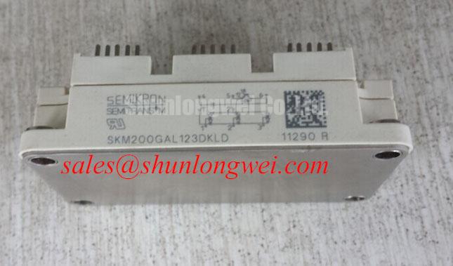
Assembly Integrity & Layout Architecture: Implementing Overvoltage Trip Prevention via Fast Switching for SKM200GAL123DKLD
Overvoltage trip prevention begins with the commutation loop, the braking path, and the DC-link measurement point. A braking IGBT and high-power ballast resistor must be selected by the system designer according to the motor or load deceleration energy, DC-link voltage range, pulse duration, repetition rate, resistor thermal capacity, and the actual switching pattern. The 1200.0 V rating of the SKM200GAL123DKLD is an official module specification; it is not a substitute for measuring switching overshoot at the module terminals.
During a service inspection, trace the positive and negative DC-link conductors from the capacitor bank to the module and braking branch. Keep the high-current commutation path compact, use mechanically secure busbar joints, and separate sensitive gate or desaturation wiring from high di/dt conductors. The layout objective is to reduce parasitic inductance that can add voltage overshoot during turn-off. Final clearance and creepage dimensions remain system-dependent and should be checked against the insulation structure, pollution environment, working voltage, and applicable equipment standard.
The braking resistor should be evaluated for both instantaneous pulse energy and accumulated thermal loading. A resistor that survives one deceleration event may still overheat during repeated duty. Check its mounting surface, airflow, pulse rating, and thermal feedback arrangement. The braking IGBT gate circuit should be reviewed together with the main switching devices because a delayed or noisy turn-on can leave the DC link exposed during regeneration.
For a suspected overvoltage event, capture the voltage directly at the module power terminals with an appropriately rated differential probe and a short measurement loop. Compare the waveform during acceleration, steady operation, and commanded deceleration. A trip that disappears when the load is reduced may involve DC-link energy, commutation layout, gate timing, or braking control interaction; do not assign the fault to the IGBT module without separating these conditions.
In related topology evaluations, the SKM200GAL126D can be reviewed as a same-family reference point. It should not be treated as an automatic substitute, because voltage class, switching behavior, pin configuration, thermal interface, and driver requirements must match the original assembly.
Transient Dynamics & Electrical Design: Mitigating Bolted Contact Oxidation and Gate Supply Noise on SKM200GAL123DKLD
Terminal joint condition directly affects heat generation at continuous current. As a Design Consideration, a micro-ohmmeter can be used to audit a bolted power connection, with the inspection target kept below 10 µΩ where that limit is defined by the equipment design and test method. This is not an official SKM200GAL123DKLD datasheet rating. Measure the complete joint consistently, document probe placement, and compare phase-to-phase results rather than relying on a single absolute reading.
Thermographic inspection should be performed under a repeatable load after the assembly reaches a stable operating condition. Compare corresponding terminals, busbar transitions, fuse connections, and cable lugs. A localized temperature rise may be associated with contact pressure, surface condition, conductor geometry, current imbalance, or airflow. Confirm the electrical measurement before reworking the joint, then retest after the mechanical correction.
Gate power integrity requires attention to the driver supply loop, return path, isolation barrier, and local decoupling. For a high-side arrangement, bootstrap capacitor selection is an Engineering Recommendation based on the required gate charge, driver quiescent current, switching frequency, allowable supply droop, refresh interval, temperature, and capacitor derating. The required gate charge value and driver current must come from the applicable device and driver documentation; they should not be inferred from the module’s 200.0 A current rating.
Common-mode ground bounce can disturb desaturation feedback and gate-emitter control during fast switching. Route the gate command and return as a controlled pair, keep the protection sensing path away from collector-emitter power transitions, and validate the driver reference under the real switching current. If negative gate bias is used, the permitted value and transient behavior must be established by the driver and module documentation rather than selected as a universal repair setting.
Desaturation protection should be checked for blanking behavior, soft turn-off response, fault latch operation, and reset sequencing. A short-circuit test must be carried out under the equipment manufacturer’s controlled test conditions, with the oscilloscope observing gate-emitter voltage, collector-emitter voltage, fault feedback, and driver supply stability. The purpose is to confirm that the protection path limits stress within the applicable short-circuit safe operating area, not simply to verify that a fault signal appears.
⚡ Field Alert: Isolate and discharge the DC link before disconnecting gate, power, or auxiliary wiring, then verify the absence of hazardous voltage with an approved meter.
SKM200GAL123DKLD Circuit Protection & Reliability: Calibrating Baseplate Convexity Inspection
Thermal interface quality depends on the relationship between the module baseplate, heatsink flatness, fastener sequence, and thermal interface material. Inspect the copper baseplate for visible distortion, contamination, burrs, or pressure marks, and inspect the heatsink for damage across the complete mounting area. A convexity or flatness issue can create localized thermal resistance even when the fasteners appear tight.
As a Design Consideration, calibrated mechanical inspection should be used when the assembly shows uneven thermal performance or repeated thermal alarms. Check the heatsink surface with suitable metrology equipment and follow the module manufacturer’s permitted mounting procedure. Do not use fastener force to pull a visibly distorted baseplate into alignment; that can concentrate mechanical stress in the substrate and compromise electrical isolation.
The requested 50–80 µm thermal interface thickness is an Engineering Recommendation for a controlled assembly process, not an official SKM200GAL123DKLD specification established by the supplied product data. The actual interface thickness depends on the selected material, surface finish, application method, compression behavior, and the manufacturer’s installation instructions. Apply the material uniformly and remove excess contamination from the mounting surfaces.
Use a diagonal cross-pattern tightening sequence when the approved mechanical procedure calls for it, allowing the module to seat progressively against the heatsink. Final torque must be determined from the fastener size, washer arrangement, thread condition, module mounting instructions, and equipment design. After assembly, inspect for rocking, uneven compression, displaced interface material, or fastener bottoming.
Thermal validation should compare the module baseplate region, heatsink inlet and outlet areas, and corresponding phases under equivalent load. A phase temperature difference may come from current sharing, gate timing, airflow, interface pressure, or sensor placement. Review the complete thermal path before replacing the module again. The manufacturer’s discussion of Semikron sintering technology provides useful background on power semiconductor packaging, but it should not be interpreted as confirmation of an unlisted internal construction detail for this specific part.
SKM200GAL123DKLD Circuit Protection & Reliability: Calibrating Type 2 Coordination for IGBT Protection
Semiconductor fuse coordination must be evaluated against the complete short-circuit path, including source impedance, DC-link capacitance, busbar inductance, fuse clearing behavior, driver shutdown, and the module’s short-circuit withstand conditions. A Type 2 coordination assessment is not established by the 1200.0 V and 200.0 A ratings alone. The fuse total clearing I²t, peak let-through current, prospective fault current, voltage capability, and installation geometry must be matched to the equipment protection study.
Place the high-speed semiconductor fuse so that the protected conductors are short, mechanically supported, and arranged to limit fault-loop inductance. Check fuse indication contacts, mounting pressure, busbar temperature, and replacement access during service. A fuse with a suitable voltage rating can still be unsuitable if its clearing energy or peak let-through current exceeds the protection capability of the switching assembly.
For a DC-link short-circuit investigation, record the fault command, gate-emitter response, collector-emitter voltage, fuse current, and DC-link voltage with instruments rated for the transient environment. Inspect the module after the event for case damage, terminal movement, cracking, or insulation degradation, but avoid treating visual condition as proof of electrical integrity. Follow-up semiconductor testing should be performed with the module isolated from parallel circuitry.
In systems combining rectification, energy storage, and an inverter bridge, the upstream device selection should be reviewed as a coordinated network. The SKM2X75-GAH126D may be examined as a related front-end or complementary-stage reference, subject to topology, current path, voltage stress, and control compatibility. For resonant heating applications, the Resonant Topologies in Home Appliances guide can provide additional topology context when evaluating commutation behavior.
Before returning an industrial inverter welder or medium-frequency induction heating supply to service, confirm the protection chain from fault detection through gate shutdown, fuse interruption, DC-link discharge, and restart interlock. The final acceptance test should use the equipment’s approved operating envelope and verify that measured transient margins remain compatible with the installed protection architecture.