Content last revised on September 11, 2026
Transient Dynamics & Electrical Design: Thermal Paste Degradation Prevention and Mounting on SKM200GAL126D
| Manufacturer | Semikron |
|---|---|
| Product Category | IGBT Module |
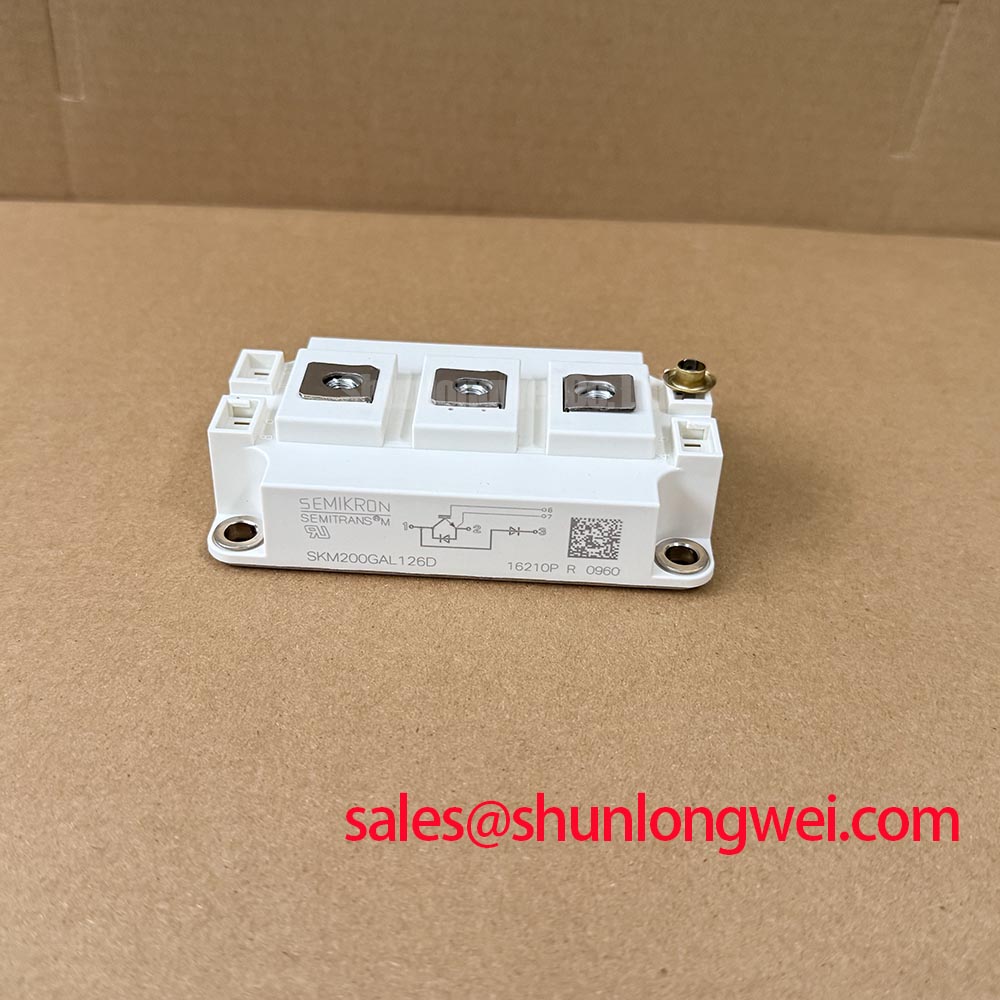
| Part Number | SKM200GAL126D |
| Official Voltage Rating | 1200 V |
| Official Current Rating | 200 A |
| Housing | Semitrans |
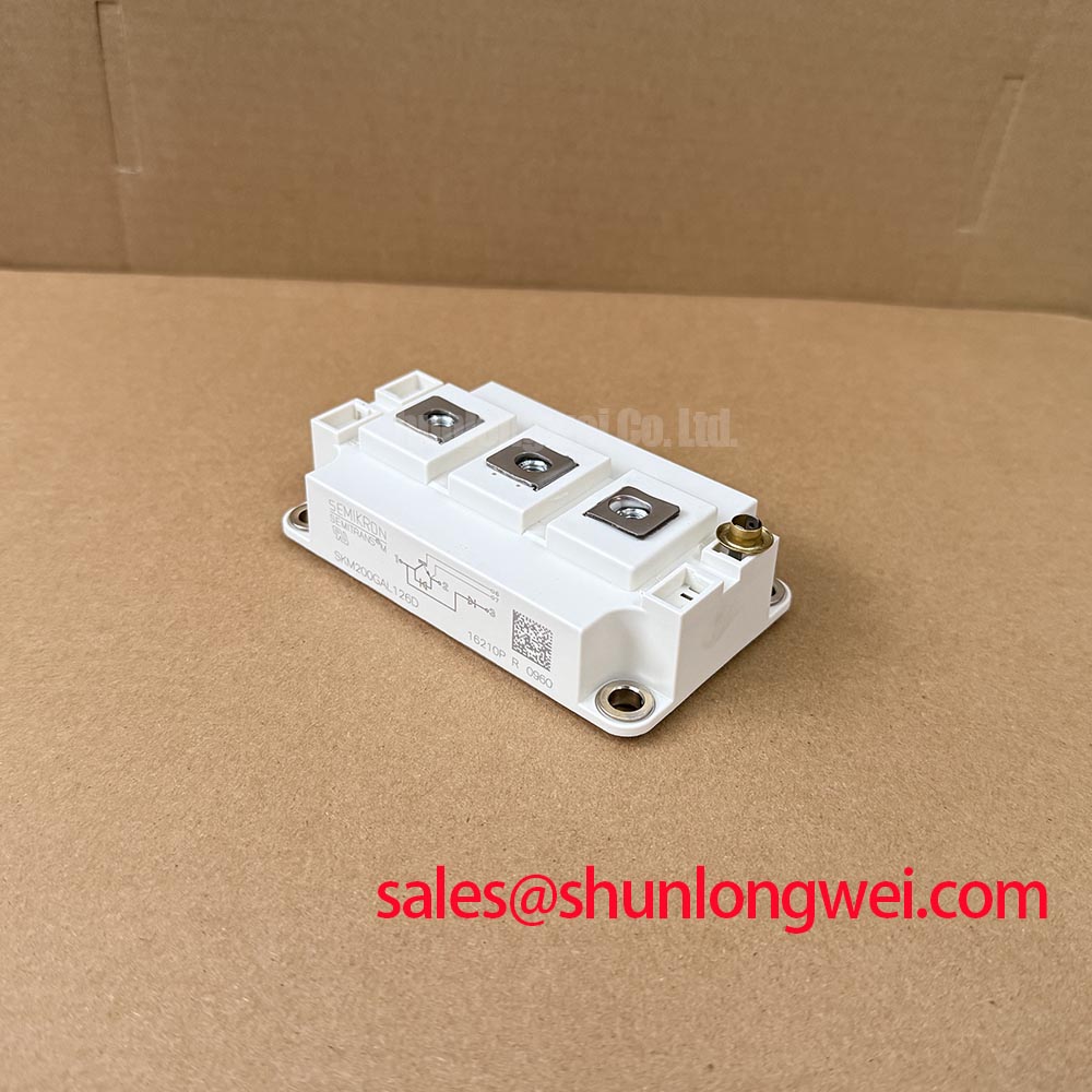
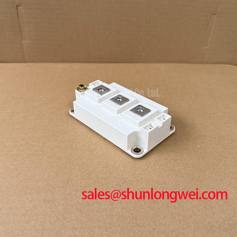
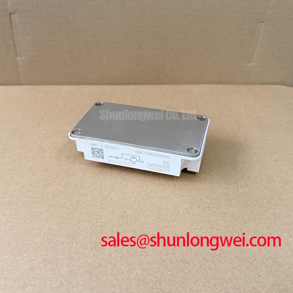
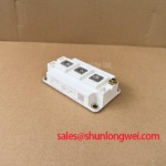
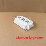
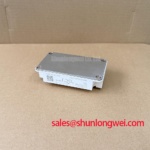
Inspect the removed module baseplate, heatsink face, and mounting hardware for dried thermal compound, visible void tracks, uneven contact marks, or mechanical distortion before installing the SKM200GAL126D. This 1200 V, 200 A Semikron IGBT module uses the Semitrans housing, so the practical objective is to restore a flat, clean, evenly loaded thermal path between its baseplate and the heatsink.
Thermal interface material should be applied as a continuous thin layer rather than as isolated blobs. A thin, continuous interface layer helps limit excessive thermal resistance while still accommodating small surface irregularities. The actual material, thickness, flatness condition, and assembly method remain system dependent. Remove hardened residue completely without scoring either mating surface, then use a sequential cross pattern when tightening mounting screws so the module does not settle under uneven mechanical stress.
During a restart investigation, compare heatsink cleanliness, cooling airflow, and fastening condition with a known stable phase position where possible. Repeated thermal alarms, unstable current loading, or uneven discoloration may indicate a problem in the wider cooling path rather than a single module fault. 💡 Pro Tip: Disconnect and discharge the DC link before handling power terminals, then tighten mounting hardware progressively in a cross pattern according to the equipment manufacturer’s screw specification.
For a heavy duty variable frequency AC motor drive, engineers should verify peak DC link stress and switching overshoot at the installed operating condition. Minimising the high current commutation loop helps suppress turn off inductive voltage rise, while the final peak margin must be confirmed with appropriately rated differential measurement equipment.
Preventing Spurious Faults: Galvanic Gate Drive Isolation, Reinforced Guidelines for SKM200GAL126D
Probe the gate command and gate return together at the module connection point when nuisance trips or unexplained switching pulses appear during motor acceleration. A distant probe ground can conceal the actual gate loop behaviour and can introduce misleading waveform artefacts. The SKM200GAL126D is rated at 1200 V and 200 A as an Official Specification, but the gate driver isolation performance belongs to the drive assembly rather than to the IGBT module itself.
Design Consideration: verify that the installed driver’s galvanic isolation barrier and common mode transient immunity are appropriate for the measured switching environment. Isolation claims such as reinforced insulation ratings above a given threshold must be checked against the gate driver manufacturer documentation and the applicable system safety design. Do not infer these characteristics from the IGBT module part number.
Check whether a Miller induced disturbance is present by observing the gate voltage during the opposite switch transition. Gate resistance, driver sink capability, active clamping arrangement, and wiring inductance interact during this interval. Where a protection response occurs only under load, inspect the return routing, driver supply stability, and the measurement reference before changing component values.
A related system topology can include rectifier or input stage devices such as the SKIM401GD128D. Its electrical role and package interface must be evaluated independently; shared voltage class alone does not establish direct substitution compatibility.
Field Diagnostics & Commissioning: Differential Gate Source Loop Routing to Suppress Oscillation in SKM200GAL126D Topologies
Measure resistance between the main power terminals before reconnecting the gate drive plugs. This quick screening step can identify an obvious power stage short, but it does not prove switching health. Follow with controlled waveform checks using the original drive schematic and safe commissioning procedures.
Design Consideration: keep the driver’s gate return path separate from the high current emitter or power return path wherever the module terminal arrangement and original design support that routing. Shared current return inductance can couple switching current into the gate loop, producing ringing, false desaturation responses, or inconsistent switching edges. The system engineer should confirm the terminal functions from the equipment documentation before changing any conductor route.
Inspect gate leads for unequal lengths, loose crimping, damaged insulation, and routing beside phase output conductors. Oscillation can arise from several interacting conditions, including probe placement, gate loop inductance, driver behaviour, DC link connection layout, and motor cable loading. Compare all phases under equivalent operating conditions instead of assigning a single cause from one waveform.
When current capacity is under review, the SKM400GAL125D provides a separate Semikron module reference for parameter comparison. Its voltage rating, current capability, package dimensions, terminal layout, driver requirements, and thermal interface must all be matched to the existing equipment before any replacement decision.
Preventing Spurious Faults: High Frequency Common Mode Bearing Current Guidelines for SKM200GAL126D
Capture phase to DC link and motor terminal waveforms at the drive output when faults appear only with a long motor cable connected. Cable impedance discontinuities can reflect switching edges back toward the inverter, raising terminal stress and changing common mode behaviour. The measured response depends on cable length, cable construction, motor winding characteristics, grounding arrangement, switching conditions, and the installed output filter.
Engineering Recommendation: assess whether an output choke or dv/dt filter is required from measured motor terminal voltage and the motor manufacturer’s insulation guidance. Filter selection is determined by the complete drive system and must be validated under the actual cable and load condition. Avoid assuming that the SKM200GAL126D alone defines permissible cable length or bearing current behaviour.
Inspect grounding bonds, shield terminations, output filter connections, and phase cable routing when repetitive protection events coincide with high frequency switching activity. Fourier analysis can help separate fundamental motor content from switching related harmonic components when reviewing captured inverter output waveforms. The underlying waveform method is described in Fourier Series Decomposition for Inverter Output Waveform Harmonic Analysis.
Integrated power electronics approaches also show why driver integration, control references, and power layout must be treated as a coordinated system. For broader context on integrated semiconductor and driver arrangements, see Semikron Danfoss SKiiP® Technology. For topology level troubleshooting context, review Resonant Topologies in Home Appliances.