Content last revised on October 30, 2026
SK15DGDL12T4 Maintenance Preparation and Key Specifications
- Isolate the equipment, verify DC-link discharge, and identify the main power connections against the equipment schematic before taking cold measurements.
- Check the module seating surface, heatsink contact area, and PCB alignment for contamination, distortion, or uneven mechanical loading.
- Inspect the gate-drive connections and surrounding components before reconnecting the power stage.
- Record diode-check readings and ambient conditions so that subsequent comparisons use a consistent measurement setup.
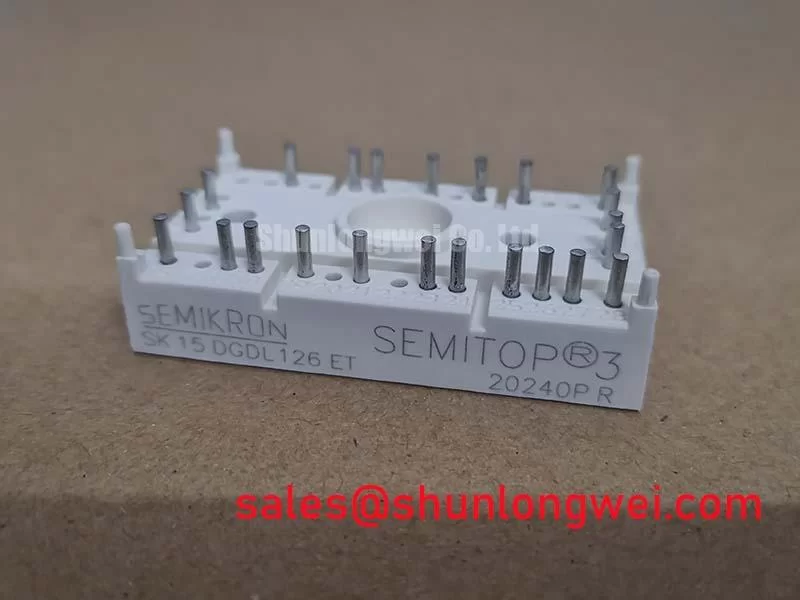
The SK15DGDL12T4 is a Semikron IGBT module in the MiniSKiiP 1 package. For maintenance planning, its electrical ratings need to stay attached to their stated temperature conditions: the continuous collector-current specification is 15 A at a case temperature of 80°C, rather than an unconditional equipment output rating.
| Parameter | Official Specification | Specified Condition |
|---|---|---|
| Collector-emitter voltage, Vces | 1200 V | Collector-emitter voltage rating |
| Continuous collector current, Ic | 15 A | Tc = 80°C |
| Collector-emitter saturation voltage, Vce(sat) | 2.25 V | Tj = 150°C; see datasheet for remaining test conditions |
| Turn-off energy dissipation, Eoff | 1.5 mJ | Tj = 150°C; see datasheet for remaining test conditions |
| Package | MiniSKiiP 1 | Semikron case designation |
These are official specification values. Consult the complete datasheet for terminal assignments, mounting instructions, switching-test conditions, and the operating curves needed for an equipment-level assessment. Saturation voltage and turn-off energy are condition-dependent characteristics, not fixed losses across every operating point.
SK15DGDL12T4 Thermal-Electrical Optimization: Main Terminal Pinout Mechanical Alignment Practical Tuning
Check PCB seating and heatsink alignment before tightening the assembly; fastening force should not compensate for a board that sits unevenly. The Semikron MiniSKiiP® Power Modules product-family information provides the relevant context for the spring-contact mounting concept. Do not transfer the terminal-stud assumptions of a different module package to this assembly.
As a Design Consideration, distinguish module mounting hardware from any bolted cable or busbar connections elsewhere in the equipment. At those external joints, check fastener engagement, washer arrangement, conductor support, and the equipment manufacturer's tightening procedure. A screw that bottoms before developing the intended clamp load can leave an apparently tight connection electrically unstable. Cable weight should be supported independently rather than carried through the board or module interface.
Inspect the contact pattern of the thermal interface during a scheduled strip-down. Uneven coverage, displaced material, contamination, or surface damage warrants checking flatness and assembly technique before fitting the replacement. The manufacturer's SKiiP® Technology information explains the broader thermal-contact technology context; model-specific assembly instructions remain the reference for the actual mounting procedure.
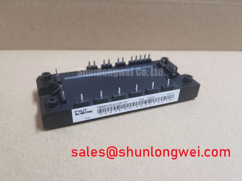
For a compact industrial inverter or high-speed CNC spindle drive, integration assessment should compare the equipment circuit, gate interface, cooling arrangement, and mechanical envelope with the original assembly. When reviewing repair materials, the SKM100GB128DN can be documented as a separate comparison candidate, not treated as a drop-in replacement. Manufacturer name or a shared voltage class does not establish matching circuitry, connections, or mounting geometry.
Field Diagnostics & Commissioning: Pre-Installation Junction Health Check: Fo in SK15DGDL12T4 Topologies
Disconnect parallel current paths before using a multimeter's diode-check function across the identified power terminals. Keep the gate in the manufacturer's specified unpowered condition and compare forward and reverse readings with the circuit diagram. Otherwise, surrounding resistors, capacitors, or semiconductor paths can dominate the measurement and obscure the module's response.
As an Engineering Recommendation, record polarity, instrument type, and terminal pair for each reading rather than reducing the inspection to a single pass-or-fail voltage. A persistent low-resistance path in both directions deserves further investigation, but an in-circuit reading alone does not identify the failed component. Compare equivalent paths under the same conditions and investigate asymmetry before applying DC power.
Screen the gate connections for an obvious short using suitable low-energy measurement equipment and ESD precautions. A handheld meter does not establish datasheet gate-leakage compliance, blocking capability, or dynamic switching health. Dedicated leakage testing requires a controlled procedure that respects the device limits and separates the module from connected driver circuitry.
If the equipment schematic labels a signal “Fo,” trace that signal to its originating driver or protection circuit before interpreting it. Do not assign an Fo terminal or built-in fault-output function to the SK15DGDL12T4 from an equipment-level label alone. The Precision Gate Drive Design engineering guide provides supporting discussion of driver referencing and protection behavior without replacing the actual equipment schematic.
During controlled commissioning, minimize the commutation-loop area to reduce inductive overshoot, and evaluate any snubber capacitor at the switching loop it is intended to control. Connection inductance can weaken its effect even when the capacitor itself is suitable. As a Design Consideration, the system engineer should establish acceptable overshoot and damping through measured switching behavior against the device limits; neither a universal loop-inductance target nor a fixed snubber value follows from the voltage rating.
Field Diagnostics & Commissioning: Thermal Stress Monitoring during High-Current Operation in SK15DGDL12T4 Topologies
Measure accessible external bolted power joints with a four-wire micro-ohmmeter while the equipment is isolated, placing the sense leads across the joint rather than an arbitrary length of conductor. Keep probe positions consistent when comparing maintenance records. This method assesses external connections; it should not be presented as a measurement of internal semiconductor resistance or spring-contact condition.
As a Design Consideration, judge contact-resistance trends against the equipment's established acceptance criteria and comparable joints. Surface preparation, conductor geometry, probe placement, and temperature all affect the result. A universal resistance threshold would conceal those differences rather than establish a dependable maintenance limit.
After controlled return to service, compare thermographic images at repeatable load and cooling conditions. Account for reflective metal surfaces and measurement access before interpreting apparent hot spots. Local heating can justify checking clamp condition and contact surfaces; a broader temperature rise also calls for inspection of airflow, filters, heatsink fouling, and thermal-interface condition.
Maintenance Note: Trend connection temperatures and inspect the cooling path during scheduled maintenance rather than waiting for a thermal trip.
Set inspection intervals from operating hours, dust exposure, loading, and observed temperature trends rather than assigning an unsupported module service life. Following cold storage or a humid shutdown, inspect for condensation and restore the equipment's approved environmental conditions before energization. Record cleaning, thermal-interface replacement, and fastening checks together so that a temperature change can be assessed against the actual maintenance work performed.