

Content last revised on October 23, 2026
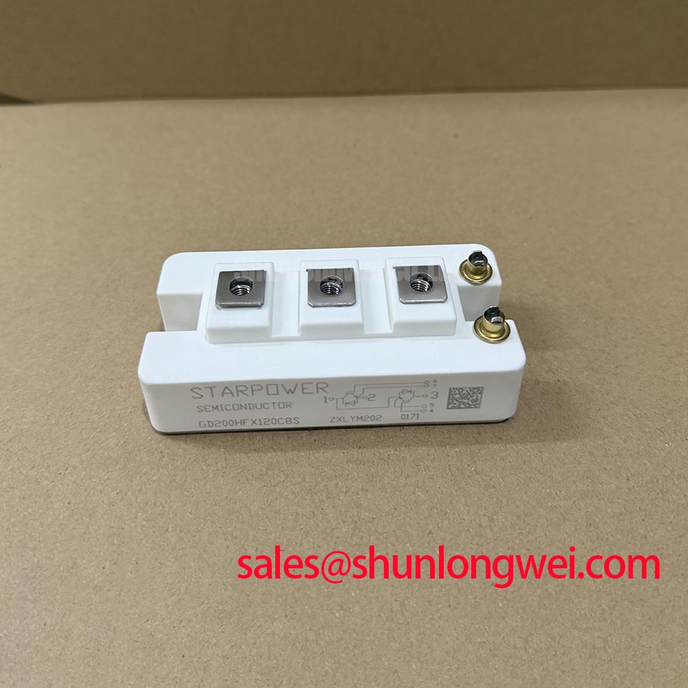
Transient Dynamics & Electrical Design: High-Speed Fault Management: VCE Desaturation on GD200HFL120C8S
When a repaired inverter trips during startup, place the gate driver in a controlled inhibit state before applying further DC-link energy. For the StarPower GD200HFL120C8S, the first engineering question is whether the desaturation circuit can recognize a short-circuit event quickly enough to protect the switching path. A practical protection architecture should distinguish type-I and type-II short-circuit behavior and complete detection and turn-off within the device’s validated short-circuit withstand limits, subject to the gate-driver IC, blanking interval, wiring inductance, and applicable operating conditions. Do not assume a particular short-circuit withstand time without manufacturer support.
The module carries an official VCES rating of 1200 V. That rating defines the collector-emitter voltage ceiling stated for the device; it does not remove the need to control turn-off overshoot generated by stray inductance. During a fault, an abrupt gate command can raise the collector-emitter voltage while current is still flowing. The protection loop should therefore be physically compact, with the desaturation sense path separated from high-current commutation conductors and referenced at the correct emitter potential defined by the gate-driver topology.
Two-stage soft turn-off is an Engineering Recommendation for evaluating this class of fault. The first stage should reduce gate drive quickly enough to limit fault current, while the second stage completes turn-off at a controlled rate to reduce inductive voltage stress. The actual gate resistance, clamping level, blanking time, and turn-off profile are system-determined values. Validate them with the intended DC-link voltage, busbar arrangement, gate driver, and current path rather than copying settings from another module.
In a field check, compare the desaturation response with a known-good driver board while monitoring the gate-emitter waveform and collector-emitter transient using suitably rated, electrically isolated measurement equipment. A fault signal appearing only after the switching node has already exceeded its expected margin may indicate excessive loop inductance, incorrect diode placement, an unsuitable sense threshold, or a gate-driver reference problem. Inspect the complete protection chain before replacing the power module again.
Regenerative braking and large braking resistors require the same transient discipline. During a deceleration event, the braking chopper and resistor must manage returned energy without allowing the DC link to approach the device voltage boundary. The resistor, chopper timing, DC-link capacitor bank, and overvoltage protection form one system. Designers should verify peak collector-emitter voltage during the actual braking profile and review the related Power Electronics Masterclass when establishing a practical test sequence.
Field Diagnostics & Commissioning: Main Power Terminal Contact Resistance in GD200HFL120C8S Topologies
Terminal heating under continuous load should be investigated at the bolted joint, not attributed to the semiconductor junction without measurement. The official collector current specification for the GD200HFL120C8S is 200 A at Tc = 100°C, so the complete current path must be assessed: busbar finish, flatness, fastener condition, terminal contact area, and torque procedure. A micro-ohmmeter audit of the assembled joint with a four-wire Kelvin connection is a suitable Design Consideration; a target below 10 μΩ may be used as a commissioning reference only when it matches the equipment owner’s joint specification and test method.
Record the cold resistance of each main terminal connection and compare the readings between equivalent phases. Follow this with a thermographic inspection under a stable operating load. A localized temperature rise at one terminal, compared with the other phase connections, may point toward uneven pressure, contamination, busbar distortion, or a poor contact surface. Thermal imaging should be interpreted with emissivity settings and surface finish in mind, and the camera profile should be compared at the same load and ambient condition.
For phase-angle conduction systems, line-frequency ripple can create repeating current and thermal patterns that are not visible during a brief no-load test. Confirm that the control angle, DC-link smoothing, and current feedback behave consistently across the operating range. The capacitor arrangement should be reviewed with the system’s ripple-current requirement; the general principles described in Decoupling Capacitors provide background on decoupling, but do not replace application-specific DC-link sizing.
RC snubbers can reduce ringing across a switching path, but their resistor, capacitor, pulse energy, and placement must be selected from measured waveforms and switching frequency. An unsuitable snubber can increase loss or create an unexpected current path. Use an oscilloscope to compare the switching-node waveform before and after the change, then verify device temperature and braking behavior at the intended operating point.
⚠️ Field Alert: Do not loosen or reconnect the main terminals while the DC link or control supply remains energized; follow the equipment isolation procedure, allow stored energy to discharge, and verify absence of voltage before inspection.
GD200HFL120C8S Thermal-Electrical Optimization: Managing High-C-Rate Battery Cycling Swing Practical Tuning
High-rate battery storage places the IGBT module in repeated transitions between power delivery and power absorption. In a commercial string inverter or micro-grid energy storage converter, a bidirectional power path can reverse power flow between the battery rack and inverter link, producing thermal swings that are controlled by switching pattern, current level, cooling capacity, and operating duration.
The specified VCE(sat) is 1.8 V typical under the datasheet test conditions. This value is directly relevant to conduction-loss estimation, but actual heat generation also depends on current waveform, junction temperature, duty cycle, and the number of conducting devices. The official switching description identifies a low tail current design for turn-off energy behavior, while the actual Eoff loss must be assessed using the applicable switching conditions. Do not transfer a loss figure from a different gate resistance or DC-link condition.
For peak shaving, map the battery current command against the inverter modulation state and the cooling system response. A short high-current interval can create a different thermal result from the same ampere-hours delivered slowly. The commissioning record should therefore include phase current, DC-link voltage, switching frequency, heatsink temperature, and the temperature trend during charge-to-discharge reversal. This makes it easier to separate electrical loss changes from airflow or thermal-interface problems.
When modules are operated in parallel, positive temperature coefficient behavior can support static current sharing in the operating region where that behavior applies, but it does not guarantee equal dynamic current during switching. Gate-loop symmetry, common-emitter inductance, busbar geometry, driver propagation delay, and individual connection resistance all influence transient sharing. Designers should keep the power and gate-current paths physically balanced, then verify current distribution with appropriately rated probes during turn-on, turn-off, regenerative braking, and fault recovery.
The thermal interface material should cover the mounting surface evenly without trapping air or contaminating the insulation boundary. Mounting flatness, heatsink condition, fastening sequence, and the equipment manufacturer’s specified torque determine the final thermal contact. Where an existing module is replaced, compare the footprint, terminal arrangement, isolation requirement, and gate-driver interface before energizing the converter. The CM200DY-12NFA may be reviewed as a separate, neutral cross-reference for engineers comparing power-module configurations; electrical and mechanical compatibility must be established independently.
Field Diagnostics & Commissioning: Pollution Degree 3 Creepage Distances in GD200HFL120C8S Topologies
Isolation testing should begin only after the module is disconnected from the gate driver, sensing circuits, capacitors, and other components that could be stressed by the test voltage. The official isolation specification for the GD200HFL120C8S is 2500 V AC for 1 minute. This rating does not by itself define a permissible field insulation-test procedure or an equivalent DC test. For a field insulation audit, use only a manufacturer-approved procedure; the terminal connections, test voltage, ramp, duration, and acceptance criteria must remain consistent with the applicable safety documentation.
Measure the circuit-to-baseplate insulation using the terminal grouping specified by the approved procedure, and document the result with the module temperature and surrounding condition. Avoid applying the insulation-test voltage across semiconductor junctions or gate-emitter terminals. A lower reading may arise from surface contamination, moisture, damaged insulation, cable coupling, or a compromised ceramic substrate. Isolate the module from external wiring before making a component-level judgment, and repeat testing only as permitted by the approved procedure. Never use an insulation tester across an attached gate-driver output, control board, or sensor circuit unless that circuit is explicitly rated for the applied test.
Pollution Degree 3 environments require careful attention to dust accumulation, condensation, creepage, and the cleanliness of the enclosure. Creepage distance is determined by the complete assembly geometry, material group, working voltage, and applicable equipment standard, not by the IGBT part number alone. Keep conductive debris away from terminal edges and insulating surfaces, and inspect areas where dust can bridge between the power terminals and baseplate mounting structure.
The 2500 V AC isolation rating is an official module specification, while system-level clearance, creepage, enclosure sealing, and protective-earth construction remain integration responsibilities. If the converter is evaluated for industrial photovoltaic storage, a commercial string inverter, or a micro-grid cabinet, review the complete insulation coordination under its actual pollution, humidity, altitude, and service conditions. Any abnormal insulation trend should trigger a controlled shutdown, cleaning and drying procedure where permitted, and an approved repeat test before the DC link is restored.
| Parameter | Specified Value | Classification |
|---|---|---|
| Collector-emitter voltage, VCES | 1200 V | Official Specification |
| Collector current, IC | 200 A at Tc = 100°C | Official Specification |
| Saturation voltage, VCE(sat) | 1.8 V typical under datasheet test conditions | Official Specification |
| Turn-off behavior | Low tail current design | Official Product Description |
| Isolation voltage, VISOL | 2500 V AC for 1 minute | Official Specification |
For systems that combine encoder feedback with inverter control, review the quadrature signal path separately from the power stage. The reference on Rotary Encoders and Quadrature Signals can assist with interpreting direction and phase relationships when commissioning a servo-linked converter.