Content last revised on November 5, 2026
Transient Dynamics & Electrical Design: Junction-to-Case Thermal Network Simulation on GD300HFL120C2S
Feed the overload loss waveform into a junction-to-case thermal model rather than applying steady-state thermal resistance to a short pulse. As a Design Consideration, a multi-RC Foster network represents the measured transient response through resistance and time-constant pairs; its intermediate nodes do not represent physical layers inside the module. Use coefficients specific to the GD300HFL120C2S, keeping transistor and diode loss paths distinct. (community.infineon.com)
For an Engineering Calculation, obtain junction-temperature rise by applying the loss history to the transient thermal response, then reference that rise to case temperature at the specified measurement location. Repeated overloads require retained thermal history, including cooling intervals. Compare the resulting peak junction temperature with the applicable operating limit, not with heatsink temperature alone. (epsg.minebeamitsumi.eu)
Include switching-loss changes when assessing thermal margin. Reverse-transfer capacitance, Cres, is a capacitance, not Miller plateau charge; gate-charge information and measured switching conditions serve different purposes. The linked Unlocking Efficiency in Industrial Drives provides supplementary technology context, not GD300HFL120C2S thermal coefficients or proof of its semiconductor generation. (infineon.com)
Field Diagnostics & Commissioning: Baseplate Convexity and Screw Tightening for GD300HFL120C2S
Inspect heatsink flatness, surface contamination, and interface contact before tightening the mounting screws. As an Engineering Recommendation, control thermal-interface material through a repeatable application process and inspect coverage during assembly qualification. Follow the module-specific mounting procedure for tightening sequence and torque; do not compensate for curvature by locally overtightening fasteners or importing another package’s paste thickness. (community.infineon.com)
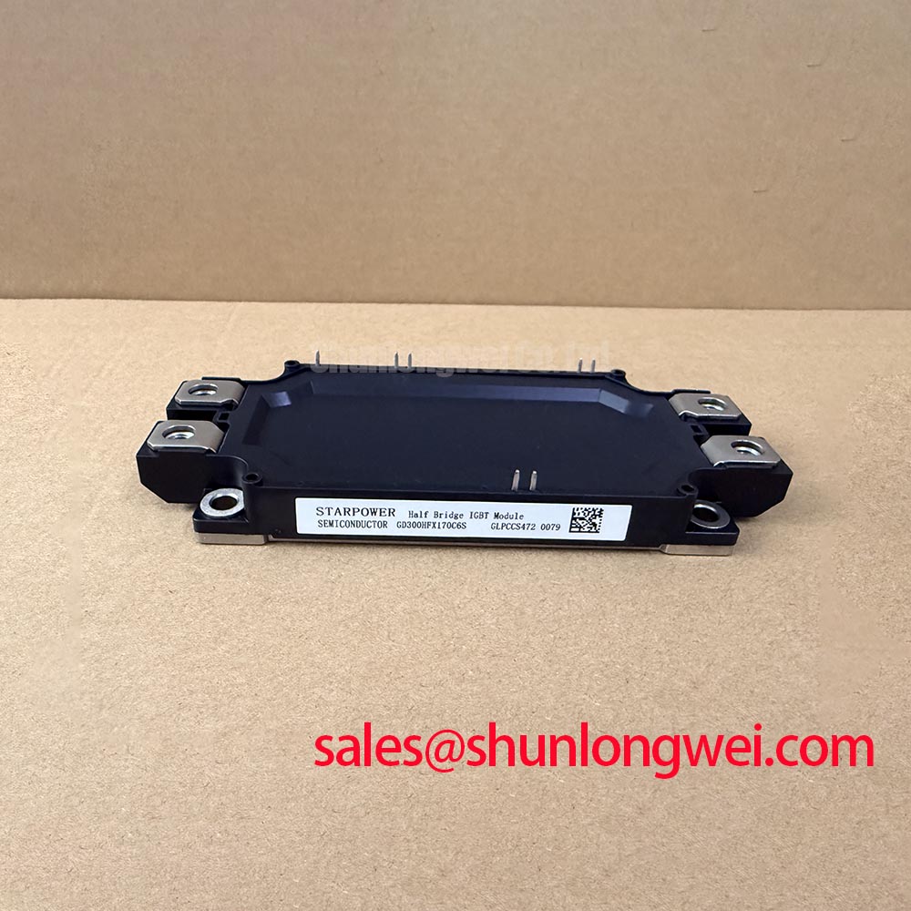
For replacement assessment, compare FF300R12ME4_B11 against the original assembly drawing and electrical requirements. Matching headline ratings establishes a comparison class, not a verified direct replacement. The following table compares headline ratings; GD300HFL120C2S values are the supplied product specifications. Consult each manufacturer's datasheet for the applicable rating conditions. (infineon.com)
| Parameter | GD300HFL120C2S | FF300R12ME4_B11 |
|---|---|---|
| Manufacturer | StarPower | Infineon |
| Voltage rating | 1200 V | 1200 V |
| Current rating (subject to datasheet conditions) | 300 A | 300 A |
| Package designation | Power Module | EconoDUAL 3 |
| Integration checks | Consult Datasheet: rating conditions, terminal map, dimensions, mounting requirements, gate drive, and insulation test conditions. | |
During assembly qualification, preserve the intended terminal spacing and prevent interface compound from contaminating electrical connections. Where an auxiliary emitter connection is identified in the terminal drawing, keep its gate-driver return separate from the main load-current route to reduce shared-inductance disturbance. This is a Design Consideration, not confirmation of a particular GD300HFL120C2S terminal arrangement. (infineon.com)
GD300HFL120C2S Operational Boundaries: Evaluating Coordination of High-Speed Fuse Arcing Voltage Limits
Check fuse total-clearing I²t and peak arc voltage at the actual circuit conditions, rather than selecting protection from the module’s current rating alone. Eaton’s semiconductor-fuse guidance distinguishes rapid electronic IGBT protection from fuse-based fault isolation: a fuse can limit consequential damage without preserving semiconductor function. Module-case containment therefore requires coordination evidence, not an assumed sub-cycle withstand rating. (eaton.com)
As a Design Consideration, evaluate prospective fault current, DC interruption capability, circuit time constant, and the voltage appearing across the protected assembly during clearing. Compare these with documented equipment withstand limits. Check creepage and clearance against the equipment’s insulation requirements; the 1200 V collector-emitter rating does not specify a terminal-to-baseplate dielectric test voltage. Infineon Automotive Qualified IGBTs describes a separate product qualification category, not a qualification attributable to this StarPower part. (eaton.com)
When reviewing an auxiliary switching stage containing BSM300GA120DN2FS, establish its actual circuit role from the schematic rather than treating it as a front-end rectifier by association. Protection coordination must follow each device’s function and documented characteristics. (slw-ele.com)
Assembly Integrity & Layout Architecture: Checking Cold-State Main Terminal Paths for GD300HFL120C2S
With the DC link isolated and verified discharged, measure each schematic-defined antiparallel diode path with the multimeter in diode-check mode, then reverse the probes and record both observations. Isolate parallel circuit paths where necessary and compare readings with a known-good assembly under matching temperature and instrument conditions. An unexpected reading warrants further investigation; it does not identify a unique failure mechanism. (community.infineon.com)
💡 Bench Tip: Use ESD-controlled handling and discharge the gate to its corresponding emitter before repeating cold-state comparisons. A multimeter can screen gross shorts, but quantified gate leakage requires a controlled semiconductor test setup using the specified bias and acceptance conditions. (infineon.com)
Before powered testing, trace the external driver and protection connections rather than assuming integrated functions from the package. Infineon Intelligent Power Modules (IPM) illustrates a distinct integration category. As an Engineering Recommendation, assess off-state bias and Miller-clamp behavior against measured gate disturbance, keeping driver-return routing away from power-current noise. (infineon.com)