


Content last revised on June 17, 2026
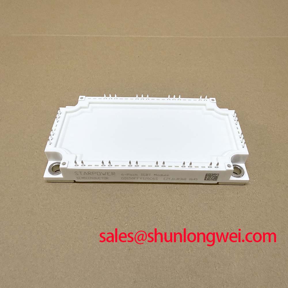
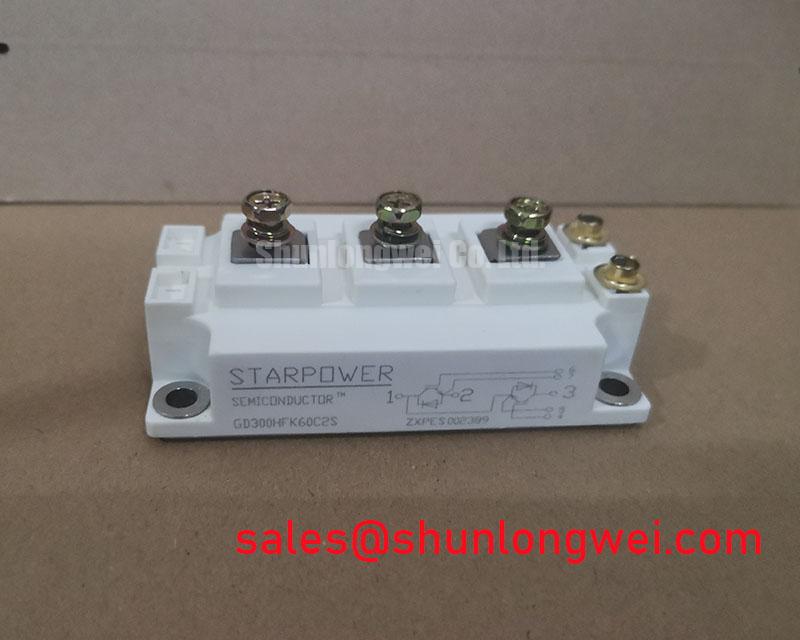
GD300HFK60C2S | 600V 300A IGBT Module for High-Efficiency Inverters
Engineered for high-frequency power conversion, the STARPOWER GD300HFK60C2S is a 600V/300A 2-Pack IGBT Module that minimizes switching losses to maximize system efficiency and power density. It integrates advanced IGBT and diode technology to deliver a robust solution for demanding industrial applications. What is the key advantage of the GD300HFK60C2S's design? It prioritizes low switching losses for higher frequency operation. With key specifications of 600V | 300A | VCE(sat) 1.8V (Typ.), this module provides the performance headroom required for modern power systems. The primary engineering benefits include significantly improved thermal performance and enhanced operational ruggedness under fault conditions. This module is particularly well-suited for engineers developing high-frequency Variable Frequency Drives (VFDs) where balancing efficiency, thermal management, and reliability is a primary design challenge. For high-frequency VFD systems up to 150kW, the GD300HFK60C2S offers an optimal balance of switching efficiency and conduction performance.
Product Details
Application Scenarios & Value
System-Level Benefits in High-Frequency Motor Drives and Inverters
The GD300HFK60C2S is engineered to excel in applications where switching frequency directly impacts system size, cost, and efficiency. Its core value is demonstrated in systems like industrial Variable Frequency Drive (VFD) systems, Uninterruptible Power Supplies (UPS), and solar inverters. In a high-frequency VFD, for example, the primary engineering challenge is managing the heat generated from switching events. The low total switching energy (E_tot) of 49 mJ (typical at 125°C) directly translates to lower power dissipation. This reduction in waste heat allows designers to specify smaller, more cost-effective heatsinks, thereby increasing the overall power density of the inverter. Furthermore, its 10µs short-circuit withstand time provides a critical layer of protection, ensuring the drive can survive fault conditions common in industrial environments, a crucial aspect of meeting safety standards like IEC 61800-5. How does the integrated NTC benefit system design? It enables direct, real-time thermal monitoring for enhanced protection. For systems requiring higher voltage blocking capabilities, such as those operating on a 480V AC line, the related GD400HFL120C2S offers a 1200V rating.
Key Parameter Overview
Decoding the Specs for Optimal Switching Performance
The technical specifications of the GD300HFK60C2S are optimized to provide a balanced performance profile, minimizing both conduction and switching losses. The parameters below detail its capabilities in a standard half-bridge (2-in-1) configuration.
| Parameter | Symbol | Conditions | Value |
|---|---|---|---|
| Absolute Maximum Ratings (T_C = 25°C unless otherwise noted) | |||
| Collector-Emitter Voltage | V_CES | T_j = 25°C | 600 V |
| Continuous Collector Current | I_C | T_C = 100°C | 300 A |
| Pulsed Collector Current | I_CM | t_p = 1ms | 600 A |
| Gate-Emitter Voltage | V_GES | - | ±20 V |
| Short Circuit Withstand Time | t_sc | V_GE ≤ 15V, T_j = 150°C, V_CC = 360V | 10 µs |
| IGBT Characteristics (T_j = 125°C unless otherwise noted) | |||
| Collector-Emitter Saturation Voltage | V_CE(sat) | I_C = 300A, V_GE = 15V | 2.2 V (Max) |
| Turn-On Switching Energy | E_on | I_C = 300A, V_CC = 300V | 27 mJ (Typ) |
| Turn-Off Switching Energy | E_off | I_C = 300A, V_CC = 300V | 22 mJ (Typ) |
| Diode Characteristics (T_j = 125°C unless otherwise noted) | |||
| Forward Voltage | V_F | I_F = 300A, V_GE = 0V | 1.9 V (Typ) |
| Reverse Recovery Energy | E_rec | I_F = 300A | 16 mJ (Typ) |
| Thermal and Module Characteristics | |||
| Thermal Resistance, Junction-to-Case | R_th(j-c) | Per IGBT | 0.085 °C/W |
| Operating Junction Temperature | T_j_op | - | -40 to +150 °C |
Technical Deep Dive
A Closer Look at the Trade-off Between VCE(sat) and Switching Energy
In IGBT design, there is a fundamental trade-off between conduction losses (defined by V_CE(sat)) and switching losses (defined by E_on and E_off). The GD300HFK60C2S is engineered to find an efficient balance point for high-frequency applications. Its typical V_CE(sat) of 1.8V at 25°C ensures that conduction losses are kept in check. Think of V_CE(sat) like the friction inside a pipe; a lower value means less energy is wasted as heat when current flows through it. However, the real strength for its target applications lies in its controlled switching energy. The total switching energy (E_on + E_off) is a measure of the power lost each time the device turns on and off. This can be compared to the energy needed to start and stop a heavy flywheel; significant energy can be consumed in the transition. By optimizing the internal chip design, STARPOWER has minimized this transitional energy loss, which becomes the dominant factor for overall efficiency as switching frequencies increase beyond 10-15 kHz. This careful balance makes the module a strong candidate for designs aiming to push operational frequencies higher without incurring prohibitive thermal management costs, a key objective in modern power converter design.
Frequently Asked Questions (FAQ)
What is the primary significance of the 10µs short-circuit withstand time for system reliability?
The 10µs short-circuit rating is a critical safety and reliability feature. It guarantees that the IGBT can survive a direct short circuit across the output for up to 10 microseconds, providing sufficient time for the system's protection circuits (like desaturation detection) to safely shut down the gate drive. This prevents catastrophic module failure, enhances equipment longevity, and is often a prerequisite for robust industrial motor drives and power supplies where such fault conditions can occur.
How does the V_CE(sat) of 2.2V (max) impact thermal design compared to a module with lower V_CE(sat) but higher switching losses?
While a lower V_CE(sat) reduces conduction losses, this often comes at the cost of higher switching losses. For applications operating at higher frequencies (e.g., >15 kHz), switching losses become the dominant source of heat. The GD300HFK60C2S, with its balanced V_CE(sat) and optimized low switching energy, will often generate less total heat in such a system than a module purely optimized for low V_CE(sat). This results in a lower junction temperature or allows for a smaller heatsink, directly impacting the system's power density and cost. For a deeper understanding of fault prevention, explore our guide on IGBT failure analysis.
For further evaluation of this module's fit within your power conversion system, please refer to the official datasheet. Detailed application notes and performance curves provide the necessary data for thermal simulations and loss calculations. This data-centric approach ensures a design that is both efficient and reliable.