

Content last revised on October 11, 2026
Assembly Integrity & Layout Architecture: Implementing Baseplate Isolation Breakdown Testing for 1MBI200N-120
- Isolate the equipment supply, discharge stored energy using the equipment procedure, and verify the DC link is deenergized before touching the module terminals.
- Disconnect paths that could distort cold resistance measurements, then compare collector, emitter, and gate readings with the circuit diagram and a known-good assembly.
- Inspect terminal seating, mounting surfaces, and busbar alignment for contamination, distortion, or uneven contact.
- Check the gate-driver connections and identify the approved insulation-test procedure before applying any test voltage.
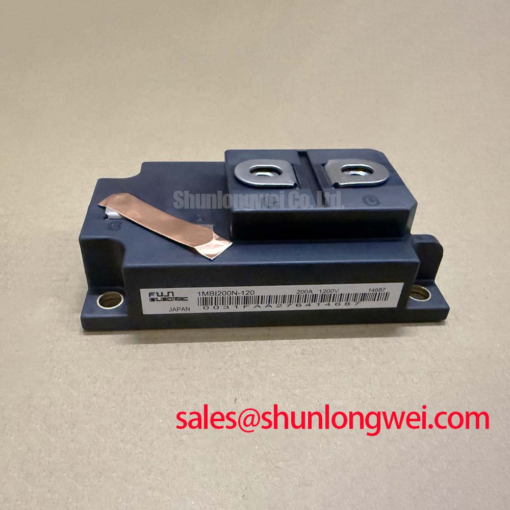
The 1MBI200N-120 from Fuji Electric is an IGBT module with supplied official ratings of 1200 V and 200 A, housed in a Fuji Power Module package. For a replacement assessment, separate these electrical identifiers from the mechanical and driver interfaces that determine whether the module can enter the existing assembly without redesign.
| Product identifier | Specification | Parameter status |
|---|---|---|
| Model | 1MBI200N-120 | Official product identification |
| Manufacturer | Fuji Electric | Official product identification |
| Rated voltage | 1200 V | Official Specification |
| Rated current | 200 A | Official Specification |
| Package | Fuji Power Module | Official Specification |
| Dimensions, terminal assignments, rating conditions, insulation limits, and mounting requirements | Consult Datasheet | Required for integration approval |
Separate the module terminals from external wiring before assessing terminal-to-baseplate insulation, because connected snubbers, driver supplies, and sensing circuits can change the measurement path. As a Design Consideration, record the connection arrangement and instrument settings so that subsequent readings describe the same assembly condition. A reading taken through the complete power stage is not equivalent to a measurement of the isolated module.
Insulation resistance screening and dielectric withstand testing answer different questions. Resistance screening checks leakage under a specified measurement condition; withstand testing applies a controlled electrical stress using a defined procedure. Do not transfer a test voltage or acceptance threshold from another module into the 1MBI200N-120 inspection plan. Use the manufacturer-approved procedure, including terminal grouping, voltage application, duration, and discharge method.
Clean accessible insulating surfaces and examine the terminal-to-baseplate region for deposited dust, moisture, tracking marks, or mechanical damage. Surface contamination can affect leakage without establishing an internal insulation failure. Conversely, an apparently clean housing does not establish internal integrity. If readings change after cleaning and drying, retain both results and investigate the surrounding equipment environment rather than assigning a single cause.
As a Design Consideration, assess clearance and creepage in the installed assembly, including adjacent busbars, fasteners, brackets, and cable movement. Preserve the equipment’s approved separation distances rather than relying on the module housing alone. After insulation testing, discharge the tested assembly before reconnecting sensitive circuits. Acceptance belongs to the defined test procedure, not to an improvised megohmmeter reading.
1MBI200N-120 Thermal-Electrical Optimization: Symmetrical Busbar Geometry for High-Current Practical Tuning
Compare the complete current paths before approving parallel operation: busbar geometry, joint resistance, gate wiring, and cooling contact all influence how the branches share load. As a Design Consideration, similar conductor lengths are useful only when their cross-sections, joint arrangements, and return paths are also comparable. A visually symmetrical layout can still contain unequal electrical impedance.
A positive temperature coefficient of collector-emitter saturation voltage can support static current sharing where the device characteristics exhibit that behavior. It must not be assumed across every current and temperature condition for this model. Evaluate the relevant saturation-voltage curves and operating region before relying on temperature feedback to balance parallel branches. Unequal cooling or contact resistance can obscure that behavior during a steady-load test.
Dynamic balance needs separate attention. Match the gate-loop arrangement and examine each branch during the same switching event, using suitable isolated measurement methods. Differences in gate resistance, driver propagation, or emitter-return impedance can produce unequal switching even when steady-state currents appear similar. Minimize parasitic power-loop inductance to reduce turn-off overshoot, then validate the resulting peak voltage under the equipment’s intended operating conditions.
During thermal assessment, correlate branch current with terminal and heatsink temperatures rather than interpreting one hot location in isolation. A hot connection can reflect local contact loss; a warmer module can also reflect unequal loading or cooling. Keep the test load repeatable and allow the assembly to approach a stable thermal condition before comparing branches.
The 2MBI150N-120 provides a related comparison point, not an automatic substitute. Compare circuit configuration, current capability, terminal placement, and mounting geometry before considering any change. For electric material-handling equipment or forklift low-voltage traction repairs, evaluate the existing power-stage requirements first; the 1200 V rating alone does not establish suitability for that application.
Field Diagnostics & Commissioning: Terminal Screw Engagement Depth in 1MBI200N-120 Topologies
Check the terminal screw, washer stack, and busbar thickness together before tightening the connection. As a Design Consideration, a screw that reaches the bottom of its threaded opening can feel secure while leaving inadequate clamping force on the conductor. Excessive engagement or forced alignment can also load the terminal structure unnecessarily.
Establish the permitted screw dimensions and tightening requirements from the mechanical documentation, then inspect the actual hardware fitted to the equipment. Include every washer and conductor layer when assessing engagement. A replacement busbar with a different thickness changes that relationship even when the mounting holes align. Avoid treating the removed fastener as proof that the same arrangement remains acceptable.
Bring the busbar into its seated position without using the terminal screw to pull it sideways or flatten it. Support connected conductors so that cable weight and movement do not impose persistent bending loads on the terminal. These are Design Considerations for the external assembly, not claims about the module’s internal joining materials.
Field Alert: A terminal screw must clamp a fully seated connection without bottoming out or forcing the busbar into alignment.
For commissioning, compare voltage drop across equivalent joints under a controlled load and inspect their temperature response. An abnormal result warrants checking the contact surfaces, hardware stack, and current path; it does not identify a unique failure mechanism. Record the assembly condition before disturbing a suspect joint, since retightening can remove useful diagnostic evidence.
When assessing electrical stress margins after the mechanical work, use the Field Engineer’s Handbook as a supporting troubleshooting reference alongside the equipment’s approved procedures. Relate measured switching peaks and thermal behavior to the applicable device limits rather than importing a generic margin into the repair decision.
1MBI200N-120 Thermal-Electrical Optimization: Negative Gate Bias vs Active Miller Clamp Practical Tuning
Measure the off-state gate-emitter waveform at the module connection while the opposite switching path commutates. As a Design Consideration, collector-voltage transitions can couple current through collector-gate capacitance and disturb the gate voltage. Probe placement and return-loop pickup matter: a waveform measured remotely at the driver can conceal the disturbance present at the device terminals.
An active Miller clamp provides a low-impedance discharge path during the relevant off-state interval. Negative gate bias changes the off-state voltage baseline. Neither approach compensates automatically for excessive loop impedance, unsuitable driver timing, or poor emitter-return routing. Select the protection arrangement against the device’s gate limits and the driver’s operating conditions, then check behavior during startup, shutdown, and protection events.
Distinguish reverse-transfer capacitance from Miller charge when comparing driver requirements. The former is voltage-dependent capacitance; the latter concerns charge transferred during a switching interval. They are related, but not interchangeable sizing values. Assess the driver’s ability to handle transient gate current while preserving the intended off-state condition, rather than choosing protection from a single headline capacitance.
If the existing driver uses a bootstrap supply, examine its voltage through the actual switching sequence, including intervals that restrict recharge. Supply droop, recharge-path behavior, and clamp timing can interact with the gate waveform. Their acceptance limits belong to the driver and equipment design; they are not additional specifications of the 1MBI200N-120.
Also correlate gate disturbance with diode commutation and power-loop ringing. Reverse-recovery behavior can influence switching noise, but no model-specific softness factor or EMC compliance follows from the supplied ratings. Fuji Electric’s RC-IGBT Modules page describes a separate manufacturer product family and should not be used to assign its characteristics to this module. Complete the commissioning check by confirming off-state gate stability and switching-voltage limits across the equipment’s approved load conditions.