


Content last revised on April 2, 2026
7MBP150KA060 IGBT Module: 600V, 150A PIM Datasheet Review
Introduction to the 7MBP150KA060 Power Integrated Module
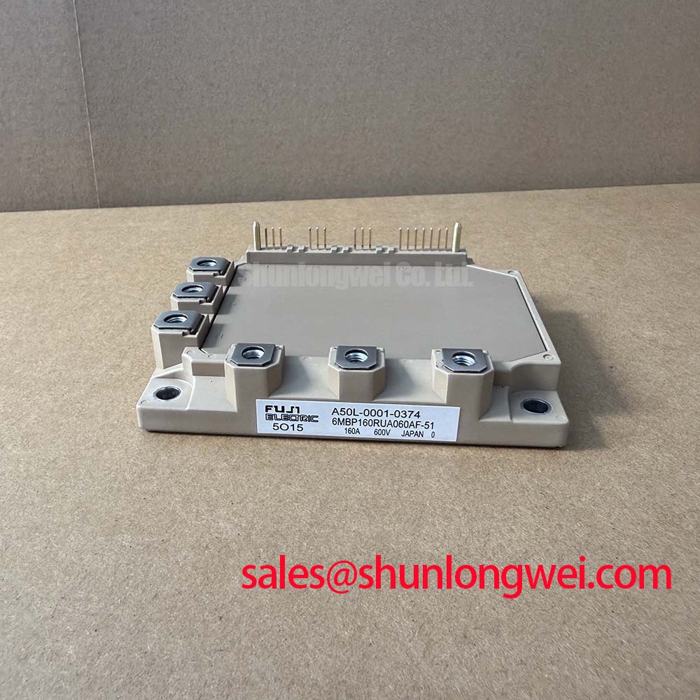
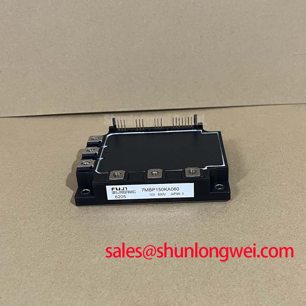
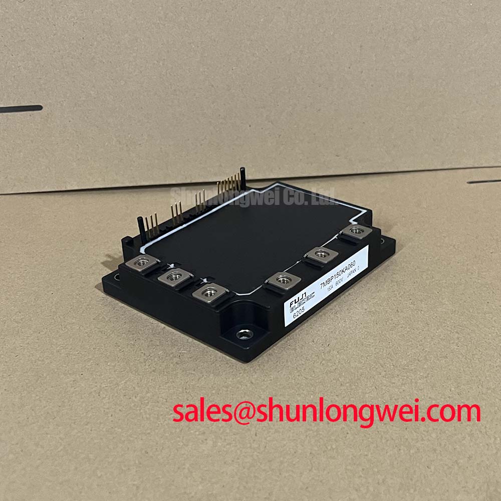
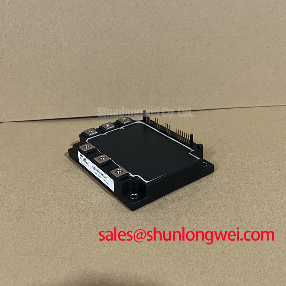
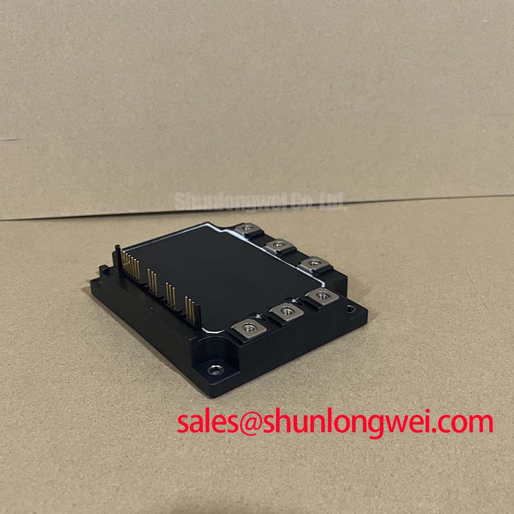
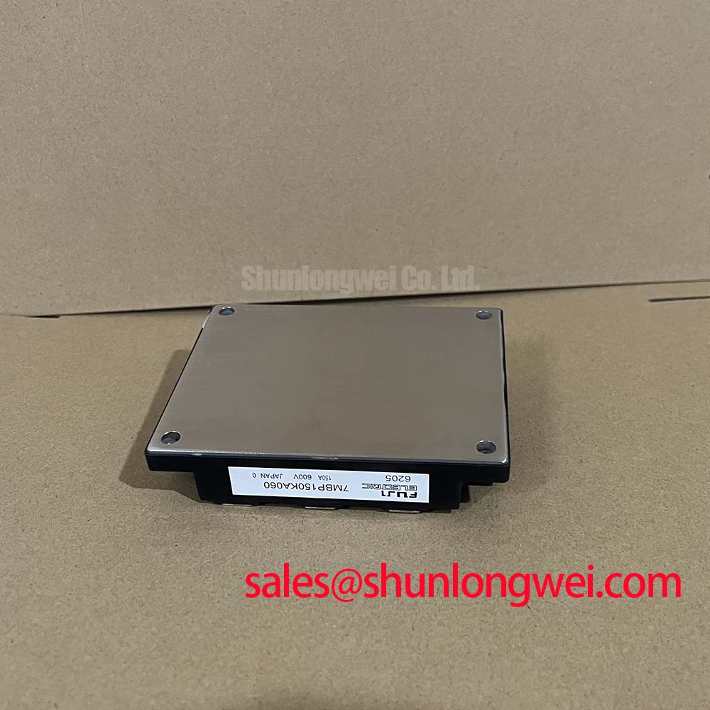
The Fuji Electric 7MBP150KA060 is a Power Integrated Module (PIM) designed to streamline the development of compact and efficient three-phase motor drives and inverters. This module consolidates a three-phase converter, a brake chopper, and a three-phase inverter into a single package, significantly reducing component count and simplifying system assembly. With core specifications of 600V | 150A | VCE(sat) 2.7V max, it delivers a robust foundation for power conversion stages. Key engineering benefits include a simplified thermal management strategy and a reduced PCB footprint. For engineers questioning how to accelerate the design cycle for small to medium-sized drives, the 7MBP150KA060's high level of integration provides a direct answer by minimizing external circuitry and connections.
Intra-Series Comparison & Positioning
System Integration: 7-in-1 vs. Discrete Solutions
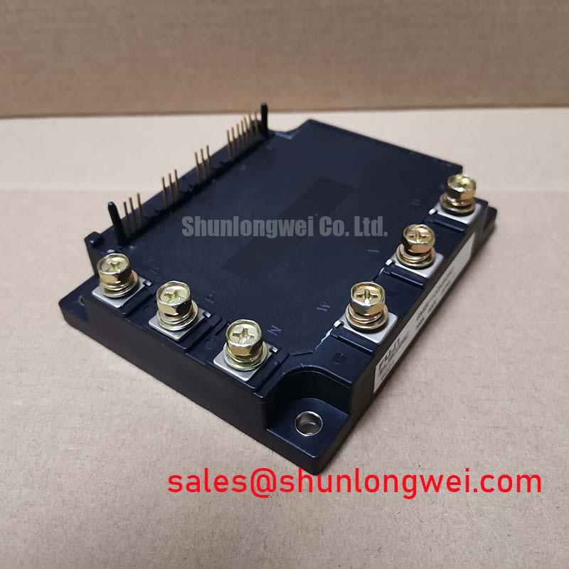
The defining characteristic of the 7MBP150KA060 is its "7-in-1" configuration. This architecture integrates seven IGBTs and their corresponding freewheeling diodes (FWDs) into one housing. This contrasts sharply with discrete or 6-pack module designs, which require separate components for the input rectification and braking circuits. The primary engineering value lies in the reduction of assembly complexity, inventory management, and potential points of failure associated with multiple solder joints and connections. For designs in the 15-30 kW class, the integrated approach of the 7MBP150KA060 presents a compelling case for reducing both manufacturing time and overall system size.
Technical Deep Dive
Harnessing the PIM Architecture for Simplified Designs
The internal topology of the Fuji Electric 7MBP150KA060 is engineered for maximum design simplification. It incorporates a three-phase converter bridge using six diodes, an inverter stage with six IGBTs and six FWDs, and a brake circuit consisting of one IGBT and one FWD. What is the main advantage of this integrated topology? It provides a pre-validated power stage, allowing engineers to focus on control logic and system-level features rather than the intricacies of power component layout and parasitic inductance management. This module also includes a built-in thermistor, which is crucial for implementing over-temperature protection without needing an external temperature sensor mounted near the power devices. This feature further streamlines the control and protection circuitry, contributing to a more compact and reliable end product. For systems where space is constrained, such as servo drives and compact motor controllers, the module like the 6MBP150NA060, which offers a similar current rating in a different package, could be an alternative to consider based on mechanical constraints.
Key Parameter Overview
Specifications Translated into Engineering Value
Understanding the key parameters of the 7MBP150KA060 is essential for effective system design. The following table highlights critical specifications and clarifies their direct impact on application performance.
| Parameter | Value (Max unless specified) | Engineering Meaning |
|---|---|---|
| Collector-Emitter Voltage (VCES) | 600V | Defines the maximum permissible DC bus voltage the module can block, making it suitable for 200/240 VAC line applications with a significant safety margin against voltage transients. |
| Collector Current (IC) | 150A (TC = 80°C) | Specifies the maximum continuous current the inverter IGBTs can handle at a standard case temperature, dictating the module's output power capability for motor drive applications. |
| Collector-Emitter Saturation Voltage (VCE(sat)) | 2.7V | This parameter is analogous to the 'on-state' resistance of the switch. A lower VCE(sat), like that found in modules such as the 7MBR150VR120, means less power is dissipated as heat during conduction, which directly improves overall system efficiency and simplifies heatsink requirements. |
| Short Circuit Withstand Time (tSC) | ≥ 10µs (VCC = 400V, Tj = 125°C) | This is a critical reliability metric, indicating the duration the IGBT can survive a direct short-circuit condition before catastrophic failure. The 10µs rating provides sufficient time for protection circuits to detect the fault and safely shut down the system. |
| Thermal Resistance (Rth(j-c)) | 0.19 °C/W (Inverter IGBT) | Represents the efficiency of heat transfer from the semiconductor junction to the module's case. A lower value signifies better thermal performance, enabling higher power density or operation in more demanding ambient conditions. For more on this critical parameter, see our guide on unlocking IGBT thermal performance. |
Application Scenarios & Value
Where Integration Accelerates Development
The 7MBP150KA060 is particularly well-suited for applications where development speed, reliability, and a compact form factor are primary design drivers. Its integrated nature makes it a strong candidate for:
- General-Purpose Inverters: For three-phase AC motor control up to approximately 22 kW, this module provides a nearly complete power stage, reducing assembly time and cost.
- Servo Drives: In robotics and CNC machinery, the compact footprint and integrated braking circuit are advantageous for designing high-density, dynamic servo amplifiers.
- Uninterruptible Power Supplies (UPS): The module's robust 7-in-1 configuration simplifies the design of the inverter and battery charging/rectifier stages in small to mid-sized UPS systems.
Due to its 150A current rating at a case temperature of 80°C, this module is the optimal choice for 240V-class drives requiring high torque output in a thermally constrained enclosure.
Industry Insights & Strategic Advantage
Meeting the Demand for Higher Power Density
The industrial automation landscape continues to trend towards smaller, more powerful, and more intelligent devices. Power modules like the 7MBP150KA060 directly support this evolution. By integrating the rectifier, inverter, and brake functions, manufacturers can develop smaller machine controllers and drives, enabling more decentralized and modular factory automation concepts. This level of integration aligns with the need for simplified supply chains and faster assembly processes, which are critical for maintaining a competitive edge. Understanding the principles of such integrated components is fundamental, as explored in the analysis of IGBT modules as the backbone of power systems.
Success Stories / Deployment Snippets
From Component to Core System Enabler
While specific customer deployments are proprietary, a common application narrative for the 7MBP150KA060 involves upgrading legacy motor drive designs. Engineers tasked with modernizing a 15 kW inverter previously built with discrete IGBTs and a separate diode bridge module were able to reduce the power stage PCB area by over 40% by adopting this PIM. This reduction not only allowed for a smaller overall product enclosure but also simplified the thermal design, as a single, flat heatsink could be used for the entire power section, improving thermal consistency and long-term reliability.
Frequently Asked Questions (FAQ)
The main benefit is system simplification. It integrates the input rectifier, output inverter, and brake chopper into a single component, which reduces assembly complexity, saves significant PCB space, and minimizes potential failure points compared to using discrete components.
Yes, the integrated NTC thermistor is placed to provide a reliable reading of the module's internal temperature. When properly interfaced with the system's control logic, it allows for effective implementation of over-temperature protection, which is crucial for preventing thermal runaway and ensuring long-term operational reliability.
The VCE(sat) directly determines the conduction losses (heat generated) when the IGBT is on. A VCE(sat) of 2.7V at 150A means that for every moment the switch is conducting its full rated current, it is dissipating approximately 405 watts (P = V * I). This value is a critical input for calculating the required heatsink performance to keep the junction temperature within safe operating limits.
While paralleling IGBT modules is a common technique, it requires careful consideration of gate drive design and thermal balancing. For a PIM like the 7MBP150KA060, it is generally not recommended without extensive engineering analysis. For applications requiring higher current, selecting a single module with a higher rating, such as the 2MBI200VA-060, is typically the more reliable and straightforward design path.
The datasheet specifies a recommended gate-emitter voltage (VGE) of +15V for turn-on and -5V to -10V for turn-off. Using a negative voltage for turn-off is critical to ensure immunity against noise-induced turn-on, especially in high dV/dt environments typical of motor drive applications.
Future-Proofing Your Power Stage Design
As system requirements evolve towards greater integration and efficiency, components like the Fuji Electric 7MBP150KA060 offer a clear path forward. The design philosophy behind this Power Integrated Module is not just about combining components; it's about providing a pre-engineered solution that de-risks the power electronics design phase. By abstracting the complexity of the power stage into a single, reliable block, engineers are empowered to allocate more resources to developing advanced control algorithms, enhancing user interfaces, and accelerating their product's time-to-market. This approach represents a strategic shift from component-level design to system-level innovation.