


Content last revised on June 30, 2026
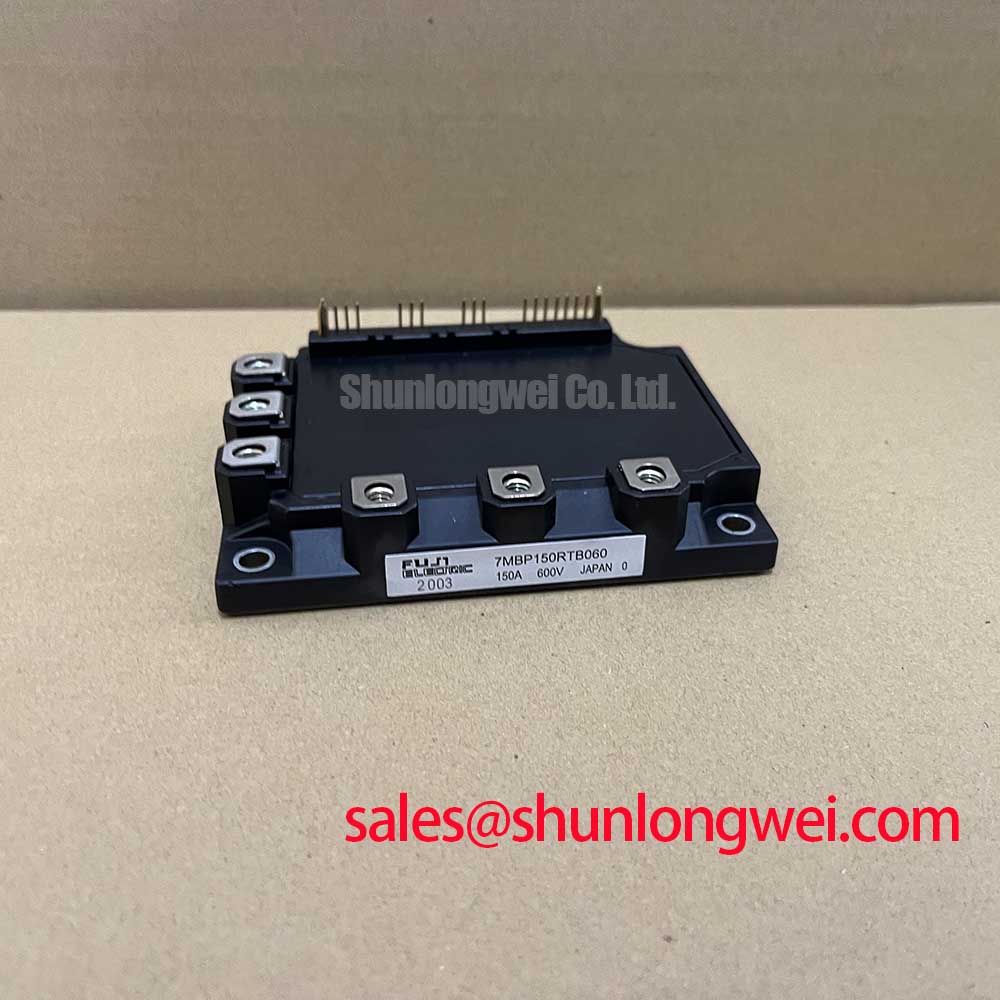
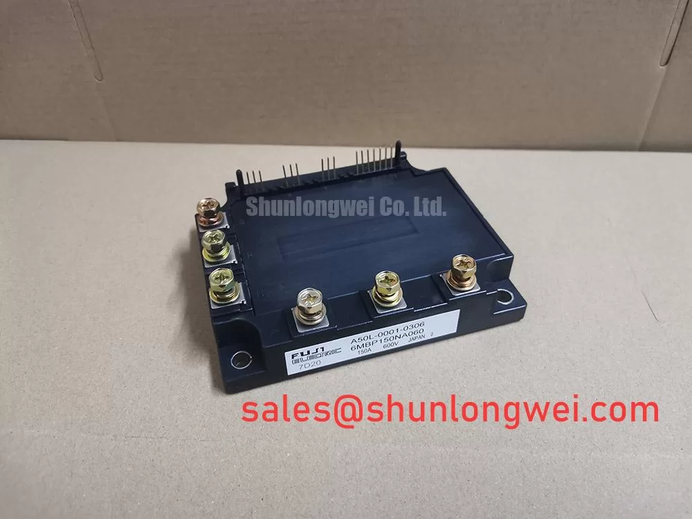
6MBP150NA060 | 600V 150A 6-in-1 Intelligent Power Module (IPM)
Product Overview
Integrated Power Stage for Accelerated Development and Enhanced Reliability
The Fuji Electric 6MBP150NA060 is an advanced Intelligent Power Module (IPM) designed to streamline the development of compact and highly reliable inverter systems. This module provides a fully integrated three-phase power stage, engineered to deliver robust performance in demanding motor control and power conversion applications. Its core value lies in simplifying the complex tasks of gate drive design and protection implementation, allowing engineering teams to focus on system-level innovation. What is the primary benefit of its integrated design? It provides a validated, self-contained protection ecosystem that enhances operational robustness.
- Core Specifications: 600V | 150A | Tj(max) 150°C
- Key Benefit 1: Drastically reduced design complexity.
- Key Benefit 2: Superior system-level reliability.
Answering a critical engineering question: this IPM improves system reliability over discrete solutions by integrating optimized gate drivers and a suite of protection circuits—including overcurrent, short-circuit, and over-temperature—that react faster and more predictably than external implementations. For industrial motor drives up to 45kW, this IPM offers the optimal balance of integrated protection, thermal performance, and design simplicity.
Key Parameter Overview
Decoding the Specs for Reliable Power Delivery
The 6MBP150NA060 is defined by parameters that ensure efficient and robust operation within its target applications. The collector-emitter voltage (VCES) of 600V provides a dependable safety margin for systems operating on 200-240V AC lines. Its 150A continuous collector current rating (IC) enables it to drive significant motor loads. A critical parameter for efficiency is the collector-emitter saturation voltage (VCE(sat)). Think of VCE(sat) as the 'friction' the current experiences when the IGBT switch is fully on. A low VCE(sat) is like a well-oiled bearing versus a rusty one; less energy is wasted as heat, allowing the system to run cooler and more efficiently.
| Parameter | Symbol | Condition | Value |
|---|---|---|---|
| Collector-Emitter Voltage | VCES | VGE = 0V | 600 V |
| Continuous Collector Current | IC | TC = 80°C | 150 A |
| Collector-Emitter Saturation Voltage | VCE(sat) | IC = 150A, VGE = 15V | 2.2 V (Typ.) / 2.7 V (Max.) |
| Maximum Junction Temperature | Tj(max) | - | 150 °C |
| Isolation Voltage | Visol | AC, 1 minute | 2500 Vrms |
Application Scenarios & Value
Achieving System-Level Benefits in Industrial Motion Control
Best fit: The 6MBP150NA060 excels in applications where reliability and uptime are paramount, such as in Variable Frequency Drives (VFDs) for conveyor systems, pumps, and fans, as well as in industrial Servo Drives. Consider a VFD controlling a high-inertia conveyor belt. During startup or a sudden jam, the motor can draw immense overcurrent, potentially destroying discrete IGBTs before an external protection circuit can react. The 6MBP150NA060 mitigates this risk through its integrated overcurrent and short-circuit protection. This internal, tightly-coupled monitoring provides a much faster response than solutions relying on external sense resistors, shutting down the IGBTs in microseconds to prevent failure. This not only protects the power module but also enhances the overall robustness of the entire drive, reducing costly downtime. For systems requiring higher power output, the 6MBP200RA060 provides a 200A alternative within a compatible package family.
Frequently Asked Questions (FAQ)
What is the primary function of the Fo (fault output) signal pin?
The Fo pin is an open-emitter output that provides a direct diagnostic signal to the system's microcontroller. When a fault condition is detected by the IPM—such as overcurrent, short-circuit, over-temperature, or supply under-voltage—the Fo pin transitions to a low state. This allows the controller to immediately initiate a safe shutdown procedure and log the specific fault, which is crucial for system diagnostics and rapid troubleshooting.
How does the integrated under-voltage (UV) lockout protect the IGBTs?
The UV lockout circuit monitors the control supply voltage (+15V). If this voltage drops below a safe threshold, the IPM automatically disables the gate drive signals to the IGBTs. This prevents the IGBTs from operating in their linear region, a condition that can occur with insufficient gate voltage and leads to very high power dissipation and rapid destruction. It's a critical feature for ensuring system stability during power-up, power-down, and brownout events.
What are the main considerations for heatsink selection with this IPM?
The primary goal is to keep the module's junction temperature (Tj) below the 150°C maximum under all operating conditions. The key parameter from the datasheet is the thermal resistance from junction to case (Rth(j-c)). Engineers must calculate the total power loss (conduction and switching losses) and use this, along with the thermal resistance of the thermal interface material (TIM) and the heatsink itself, to ensure the temperature rise is acceptable. A well-designed thermal solution is fundamental to achieving long-term reliability. For a deeper understanding, explore this guide on Mastering IGBT Thermal Management.
Can the 6MBP150NA060 be used in hard-switching Power Factor Correction (PFC) circuits?
While primarily designed for motor inverter stages, the 6MBP150NA060's electrical characteristics make it suitable for use in boost-type PFC circuits, particularly in three-phase applications common in industrial power supplies and UPS systems. Its fast-recovery freewheeling diodes (FWDs) and the controlled switching characteristics of the IGBTs are well-suited for the typical operating frequencies (up to 20 kHz) of such topologies.
Technical Deep Dive
An Inside Look at Integrated Protection Mechanisms
The engineering value of an IPM like the 6MBP150NA060 extends beyond its power handling specifications; its true advantage lies in its pre-validated, integrated protection architecture. This architecture solves a significant reliability challenge faced in discrete designs: parasitic inductance in the current sensing path. In a discrete solution, an external sense resistor and comparator circuit are used to detect overcurrent. The wiring between the IGBT emitter, the resistor, and the comparator introduces stray inductance, which can delay the protection circuit's response time. During a severe short-circuit event, even a few hundred nanoseconds of delay can be catastrophic.
The 6MBP150NA060 integrates the current sensing and protection logic directly within the module. This co-packaged design minimizes parasitic inductance to a negligible level. The integrated short-circuit protection acts like a car's airbag system. It's a self-contained safety feature that deploys microseconds after detecting a catastrophic event—far faster than a driver (the external control board) could ever react—thus preventing irreparable damage to the engine (the IGBTs). This built-in, high-speed protection provides a level of robustness that is difficult and costly to achieve with discrete components, making it a strategic choice for high-reliability systems.
Strategic Implications for System Design
Accelerating Time-to-Market with Pre-Validated Power Stages
Opting for an Intelligent Power Module such as the 6MBP150NA060 is a strategic decision that shifts engineering resources from the component level to the system level. By leveraging a pre-engineered and validated power stage, design teams can bypass the time-consuming and resource-intensive processes of IGBT selection, gate driver optimization, protection circuit design, and thermal interfacing. This approach not only reduces the bill of materials (BOM) and shrinks the PCB footprint but more importantly, it de-risks the project schedule. The module's integrated nature ensures predictable performance and reliability, allowing engineers to dedicate more time to application-specific software, user interface development, and overall system optimization, ultimately leading to a faster and more competitive market entry. Explore further insights on the strategic advantages of IPMs over discrete designs.