


Content last revised on September 30, 2026
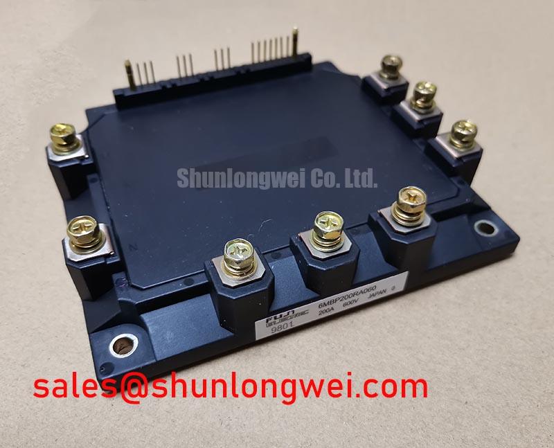
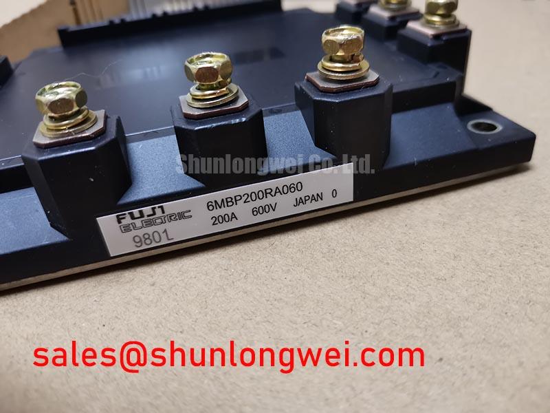
6MBP200RA060 | Fuji Electric | IPM Module | Fuji Power Module package | Rated voltage: 600 V | Rated current: 200 A (Official Specifications)
Field Diagnostics & Commissioning: Checking Drive Loop Geometry in 6MBP200RA060 Topologies
Probe the module control signals and the associated supply return during a controlled switching test, then compare any unexpected pulse or fault indication with the waveform at the controller. The 6MBP200RA060 is a Fuji Electric IPM Module rated at 600 V and 200 A (Official Specifications). Those ratings identify electrical boundaries; they do not establish the control pinout, required supply, or internal gate connection. Match each harness conductor to the equipment schematic and the module documentation before connecting a replacement.
Gate loop geometry matters, but an IPM should not be treated as though its internal IGBT gates and emitter returns are necessarily exposed. A layout review should distinguish the external control reference from high current power paths and keep the reference path clear of switching current where the documented interface permits. This is a Design Consideration intended to limit noise coupling, not a claim that this model provides a separate Kelvin emitter terminal. If a fault appears only during switching, inspect connector seating, return continuity, grounding, and controller waveforms before attributing it to the module.
Keep the DC link current path compact and compare the measured turn off voltage peak with the module’s 600 V rating under the actual operating conditions. 💡 Pro Tip: Route paired power conductors symmetrically to limit turn off overshoot, then verify the resulting voltage margin during a controlled switching test. Fuji Electric’s power semiconductor and IPM information provides manufacturer context for the device family; interface details still need to match the exact module and equipment documentation.
6MBP200RA060 Operational Boundaries: Evaluating Dynamic Braking Chopper Operation Limits
Trace the deceleration energy path from the motor terminals through the DC link before assigning a braking fault to the 6MBP200RA060. Determine from the equipment schematic whether a braking chopper is present and whether its switch is external to the IPM. The module’s 600 V and 200 A ratings (Official Specifications) do not, by themselves, specify braking energy capacity or establish that a braking IGBT and resistor are inside this package.
For a system with an external braking circuit, examine the DC link voltage and chopper command during deceleration, then check the resistor and its connections against the equipment design. Resistor energy handling depends on the load, deceleration profile, and repetition rate; the system designer must establish those limits. A voltage rise can have several causes, including an interrupted resistor path or a control issue, so compare the measured command and voltage with a known operating sequence rather than inferring a single failed part.
Switching transients also deserve attention when evaluating apparent braking or inverter faults. As a Design Consideration, diode recovery and wiring inductance can affect voltage overshoot and emitted noise, but the presence and recovery characteristics of a particular internal diode must not be assumed from the ratings alone. Review the actual power schematic, inspect the installed snubber path if one exists, and measure switching waveforms before changing components. Material on wide bandgap power devices can help frame a broader switching margin comparison; it does not change the ratings of this Fuji Electric IPM.
Preventing Spurious Faults: Parallel Current Sharing Guidelines for 6MBP200RA060
Measure each module branch current during a controlled load test if the equipment uses multiple 6MBP200RA060 units in parallel. First confirm that the original circuit was designed for parallel operation; matching voltage and current ratings alone cannot establish that two IPMs will share current safely. Compare power conductor length, connection condition, cooling contact, and control timing between branches, then investigate any persistent difference in the measured currents.
Positive temperature coefficient behaviour is sometimes considered in static IGBT current sharing, but its usefulness depends on the device characteristics and operating point. It is therefore a Design Consideration, not an asserted specification of this model. Dynamic sharing requires a separate check: unequal power path inductance or command timing can produce different switching currents even when steady state readings appear close. Capture branch waveforms under representative conditions and assess each unit’s measured current against its 200 A rating and the applicable operating limits.
For repair sourcing, 6MBP30RTA060 is a distinct Fuji Electric model to compare, not a drop in replacement established by a similar name. Check its ratings, package drawing, terminal assignment, control interface, and protection behaviour against the original equipment requirements before considering a change. The same comparison applies to modules elsewhere in the power path, including 6MBP20JB060-03; a shared system topology does not make their electrical roles interchangeable.
6MBP200RA060 Thermal-Electrical Optimization: Checking Gate Drive Isolation and Practical Tuning
Measure the controller side supply and command signals at the installed interface when an isolation related fault appears, and compare them with the equipment’s expected sequence. Do not apply an assumed gate voltage or test directly across unidentified terminals. The Fuji Power Module package designation and the 600 V, 200 A Official Specifications do not state an isolation withstand rating, reinforced insulation status, or common mode transient immunity rating.
Where the equipment uses an isolated control supply, inspect its connections, grounding arrangement, and fault feedback path before changing switching settings. The barrier rating and required clearances are system and component documentation questions; they cannot be inferred from the IPM current rating. Compare the controller waveform with the signal observed at the documented module interface during switching. A disturbance that coincides with a power transition warrants a review of return routing and isolation components, while a continuous fault indication calls for checks of supply stability and the equipment’s protection logic.
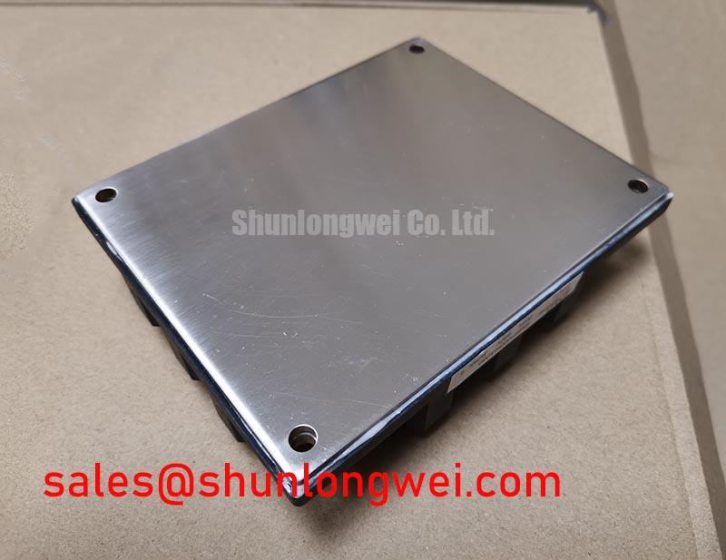
Thermal checks should be equally specific. Inspect the module mounting surface and cooling assembly for uneven contact, damaged fasteners, or obstructed airflow, then compare temperature readings across equivalent operating conditions. Select mounting force and interface material from the applicable mechanical documentation rather than a generic torque value. For an industrial inverter welder or medium frequency induction heating supply, compatibility remains a system evaluation: confirm the installed topology, cooling conditions, control interface, and measured switching margins before approving 6MBP200RA060 for service.