


Content last revised on September 26, 2026
7MBP80VCA060-51 Ratings and Replacement Assessment
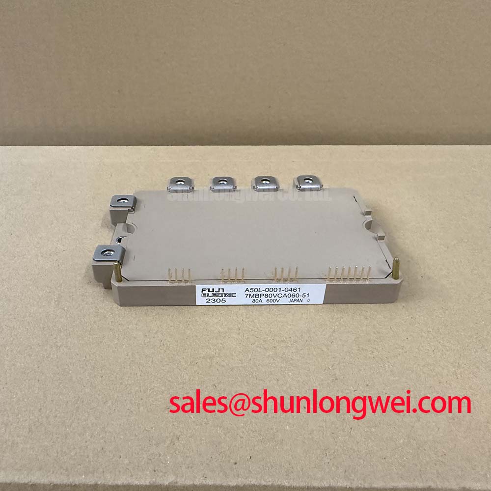
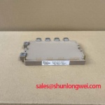
With the DC link discharged, check the installed module’s cold-state terminal readings against the service documentation before evaluating a 7MBP80VCA060-51 replacement. This Fuji Electric PIM must be assessed against both its electrical ratings and the host equipment’s gate-drive, mounting and protection arrangements; a matching current rating alone does not establish interchangeability.
| Parameter | Symbol | Official Datasheet Specification |
|---|---|---|
| Collector-emitter voltage | VCES | 600 V |
| DC collector current | IC | 80 A |
| Collector current, 1 ms pulse | ICP | 160 A |
| Collector power dissipation, per IGBT | PC | 312 W |
| Isolation voltage, 1 minute | Viso | AC 2500 V |
| Operating junction temperature | Tj | −20 to +150 °C |
The table states component ratings, not an allowable operating point for every inverter. As a Design Consideration, engineers should assess DC-link transients, switching losses, cooling conditions and protection response together before accepting the module for a particular duty cycle.
Preventing Spurious Faults: Dynamic Gate Impedance Control for 7MBP80VCA060-51
When a switching transition coincides with an unexplained inverter trip, capture the gate-to-emitter voltage at the affected switch and compare it with the controller fault record. A rapid collector-voltage change can couple through the device’s gate capacitance and disturb a nominally off switch. As a Design Consideration, a low-impedance gate turn-off path or an active Miller clamp may help limit this disturbance, but its suitability depends on the existing driver and measured switching behavior. Negative gate bias is likewise a driver-level design choice, not a specified operating requirement established by the ratings above.
Inspect the gate return path and nearby power conductors before changing driver components. Long or shared return paths can add parasitic inductance and make an apparent gate fault difficult to distinguish from measurement pickup. Route the probe reference close to the measured gate return, then repeat the observation under controlled operating conditions. If the waveform differs from a known-good phase, check driver supply integrity, connector seating and the fault-input path rather than attributing the trip to one cause.
For repair-material screening, 6MBI100L-060 can be reviewed as a separate candidate, but its circuit configuration, terminals, driver requirements and mechanical fit require independent comparison. Fuji Electric’s V-Series IGBT Application Manual provides manufacturer guidance on gate-drive and switching considerations; the host design still determines the settings used in a repair.
Assembly Integrity and Layout Architecture: Thermal Feedback for 7MBP80VCA060-51
Before fastening the module, inspect the mating heatsink for debris, damage and uneven contact. After installation, compare temperature readings at repeatable locations while the equipment follows a controlled test sequence. The −20 to +150 °C junction range is an Official Datasheet Specification, but a heatsink reading is not a direct junction-temperature measurement. As a Design Consideration, losses, thermal-interface condition and the system’s temperature-sensing location must be accounted for when interpreting that reading.
Parallel-switch current sharing needs separate static and dynamic checks. A positive temperature dependence of on-state voltage can assist static sharing under appropriate conditions, but it does not establish equal current at turn-on or turn-off for this installation. Compare gate-loop routing and power-path symmetry, then inspect switching waveforms and temperature trends under the intended load. Do not assume that devices with similar nameplate ratings will share transient current equally.
If the host uses a bootstrap supply for a high-side driver, its capacitor should be assessed against the driver’s documented gate-charge demand, quiescent consumption, leakage and the longest expected interval without refresh. That is a system-level sizing exercise, not a capacitor value specified here for the 7MBP80VCA060-51. When examining another device in the same power-conversion system, the 6MBI15L-060 has its own ratings and drive requirements; its presence elsewhere in a schematic does not establish compatibility with this PIM.
7MBP80VCA060-51 Circuit Protection and Reliability: Thermal Interface and Mounting
Look for discontinuous thermal compound coverage when removing a failed installation, while preserving the evidence needed for fault analysis. For reassembly, the Design Consideration is a continuous, appropriately thin interface without trapped voids or excess material that prevents sound contact. Confirm the heatsink flatness and follow the applicable module and equipment mounting instructions for screw sequence and torque; the ratings provided here do not specify a paste thickness or tightening value for this model. Baseplate curvature should be evaluated against the mating surface rather than corrected by forcing the fasteners.
Pro Tip: Keep the DC link isolated and verified discharged before disconnecting gate-drive or power terminals.
Protection review should connect observed faults to measured quantities: gate waveforms, DC-link voltage, phase current and temperature feedback. The stated AC 2500 V for 1 minute isolation rating is an Official Datasheet Specification, not a substitute for an equipment-level insulation assessment. As a Design Consideration, engineers evaluating unusual environmental exposure should use the equipment’s applicable qualification requirements; these component ratings alone do not establish a numerical lifetime, cosmic-ray failure rate or altitude derating.
Switching stress also depends on topology and control strategy. The discussion in Resonant Topologies in Home Appliances illustrates why switching conditions must be assessed in their circuit context, although it does not specify operating limits for this module. Fuji Electric’s power semiconductor product information is useful for distinguishing device families, not for treating another family’s characteristics as specifications for the 7MBP80VCA060-51.
7MBP80VCA060-51 Thermal-Electrical Optimization: Symmetrical Busbar Geometry
During a controlled switching test, measure collector-emitter voltage close to the module terminals and compare the observed peak with the 600 V collector-emitter rating. As an Engineering Calculation principle, turn-off voltage rises with DC-link voltage plus the contribution from stray inductance and the rate of current change. That relationship explains why a compact, balanced power path matters, but it does not supply a universal inductance target or snubber value for this inverter.
Inspect the DC-link connections for unequal paths between phases, loose joints and avoidable loop area. A symmetrical, closely coupled busbar arrangement can reduce parasitic effects; the required geometry must be verified against measured switching peaks and the equipment’s insulation and mechanical constraints. If a snubber is present, assess its condition and placement before resizing it. Changing capacitance can alter losses and switching behavior, so validation belongs in the complete circuit.
Electric forklift and material-handling traction inverters are possible compatibility-evaluation contexts, not designated applications inferred from the module rating. For an inverter with a long motor cable, compare voltage measurements at the inverter output and motor terminals: reflected-wave stress may differ between those points. Evaluate any output-filter decision against the drive, cable and motor documentation, then repeat the switching and thermal checks at the intended operating conditions.


