

Content last revised on September 20, 2026
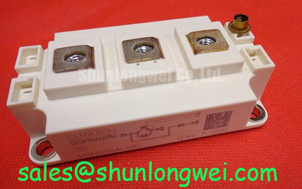
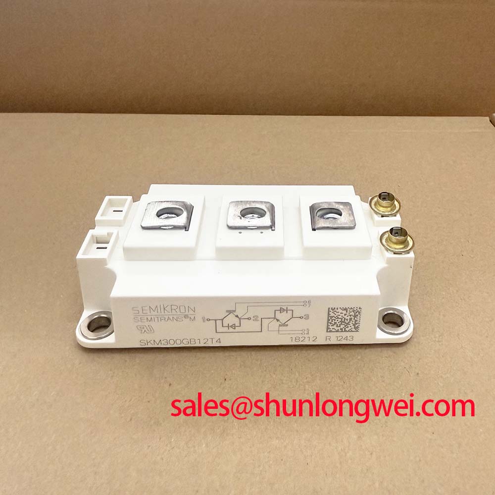
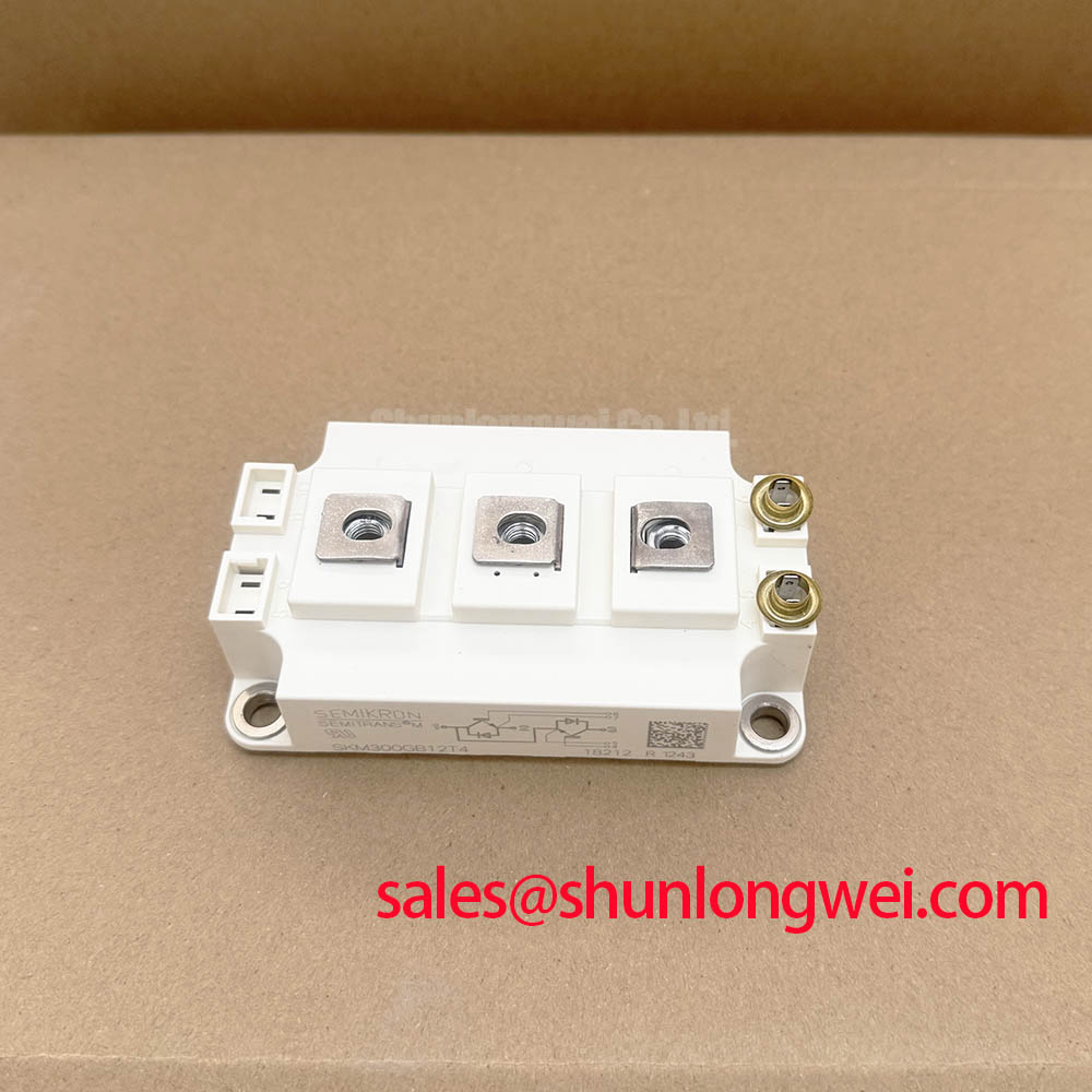
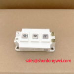
With the DC link discharged and the gate-drive harness isolated, first compare the cold-state terminal relationships of the installed unit with the drive schematic before replacing it with SKM300GB12T4. This Semikron IGBT module is rated at 1200.0 V and 300.0 A in a Semitrans housing, which are Official Datasheet Specifications supplied for this product. Confirm that the equipment bill of materials, mechanical outline, terminal arrangement, control connection, and thermal interface all correspond to the original assembly before any energised test.
A diode-mode check can help document the condition of a removed power stage, but its readings must be compared with the applicable circuit path and a known-good reference where available. The meter result is affected by parallel paths, gate-driver circuitry, DC-link capacitors, and measurement polarity. It is therefore evidence for troubleshooting rather than a stand-alone acceptance criterion. Inspect the housing, power terminals, mounting face, and insulating interfaces for visible mechanical damage or contamination, then retain the readings as a cold-state baseline for the repair record.
Bench Tip: Keep the module and gate-driver connections protected from electrostatic discharge, and record cold-state measurements before reconnecting control cables or applying a gate-drive supply.
| Product attribute | Declared value | Classification |
|---|---|---|
| Part number | SKM300GB12T4 | Product identification |
| Manufacturer | Semikron | Manufacturer identification |
| Rated voltage | 1200.0 V | Official Datasheet Specification |
| Rated current | 300.0 A | Official Datasheet Specification |
| Housing | Semitrans | Official Datasheet Specification |
For package-family context, the manufacturer’s SEMITRANS® Industry Standard IGBTs information describes the relevant power-module platform. That reference does not replace verification against the original equipment documentation for this exact part number. In a heavy-duty variable-frequency AC motor drive, the module should be evaluated as one element of a complete inverter system whose DC-link voltage, gate-driver behavior, cooling path, protection logic, and load profile determine actual operating stress.
Benchtop Waveform Tuning and Cosmic-Ray Robustness Considerations for SKM300GB12T4
Begin waveform work by confirming that the DC-link operating envelope remains appropriate for the module’s 1200.0 V Official Datasheet voltage rating. Probe the DC link and the switched power-node waveform with measurement equipment suitable for the voltage and transient environment, using a reference arrangement that does not add a misleading loop to the result. Compare startup, steady-state loading, commanded deceleration, and fault-clearing captures. A clean static measurement does not establish switching margin; only a correctly referenced dynamic measurement can reveal overshoot, ringing, or an unexpected bus excursion.
Cosmic-ray and terrestrial-neutron robustness, altitude-related effects, and Single Event Burnout rates require manufacturer-specific qualification information and system environmental data. No FIT rate, altitude threshold, burnout probability, or voltage-derating multiplier is asserted here for SKM300GB12T4. Design Consideration: where equipment will operate at elevated sites or in an environment that changes the risk assessment, the system engineer should obtain applicable manufacturer documentation, define the DC-bus operating range, and validate peak device voltage during representative switching tests. The 1200.0 V rating is an identification boundary, not a substitute for that verification.
Inspect the commutation loop as part of the bench work. DC-link capacitor connections, busbar geometry, module terminals, snubber connections, and probe attachment can all alter the waveform seen at the device. Minimise parasitic loop inductance to suppress turn-off inductive overshoot, then verify peak margins against the actual DC-link voltage with the final mechanical arrangement installed. A metal-oxide varistor or other clamp network should only be assessed as a coordinated system element: its clamping behavior, energy handling, placement, and interaction with existing suppression circuitry must be checked against the drive design rather than assumed from the module rating.
The thermal path also belongs in waveform tuning. Transient thermal impedance is a time-dependent relationship, so a short overload pulse and sustained operating current cannot be assessed from the same thermal assumption. Design Consideration: correlate heatsink temperature, loading duration, switching conditions, and the equipment’s permitted junction-temperature limits from its approved documentation. Use the module manufacturer’s full datasheet for any temperature-dependent electrical or thermal values not listed in the product identification data above.
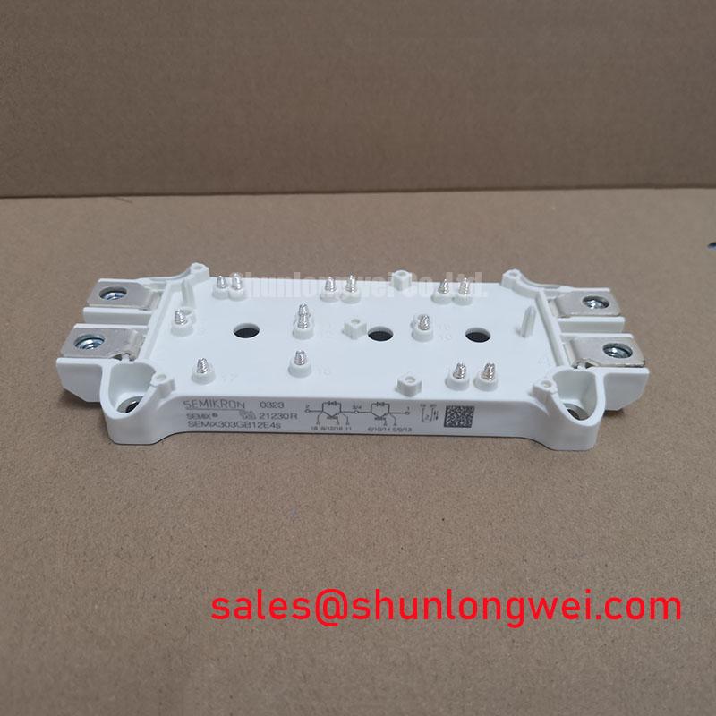
When reviewing related installed assemblies, SKM75GB07E3 can serve as a separate Semikron part-number reference. It must not be treated as an automatic electrical or mechanical substitute for SKM300GB12T4; rated voltage, current, package details, gate-drive requirements, protection settings, and the original drive documentation require independent comparison.
Preventing Spurious Faults: Reinforced Insulation Barrier Integrity Guidelines for SKM300GB12T4
Check insulation integrity as a property of the complete installed assembly, beginning with the module mounting surface, insulating hardware where fitted, heatsink condition, gate-driver isolation barrier, cable routing, and enclosure clearances. The supplied product data identifies a Semitrans housing but does not state a reinforced-isolation voltage, common-mode transient immunity value, creepage distance, clearance distance, or safety certification for SKM300GB12T4. Those values must not be inferred from the package family or from a neighboring product.
Design Consideration: establish the required isolation class from the equipment safety architecture and applicable standards, then use the manufacturer documentation for each participating part. The IGBT module, driver isolator, current sensor, power supply transformer, PCB layout, mounting system, and enclosure can each determine the final isolation performance. A discrete power module must not be presented as independently compliant with system-level EMC requirements or as proof of reinforced isolation in the assembled drive.
During incoming and repair inspection, look for conductive debris, moisture residue, damaged barriers, loosened hardware, carbon tracking, and cable insulation wear. Power-off resistance checks may reveal gross contamination or unintended connections, but they do not certify dielectric withstand capability. Where the service procedure calls for dielectric testing, use the voltage, duration, test points, discharge method, and acceptance conditions specified by the equipment manufacturer or qualified test procedure. Confirm that all energy-storage elements have been safely discharged before connecting any test fixture.
Common-mode disturbances can couple into a gate-drive circuit through routing and reference choices. Engineering Recommendation: separate sensitive control paths from high-current switching paths where the layout permits, maintain intended isolation distances, and verify command integrity under representative switching conditions. A gate pulse observed during a transient may indicate several interacting causes, including measurement setup limitations. Compare it with the known control path and inspect the driver’s reference behavior before changing the power-stage module.
SKM300GB12T4 Circuit Protection & Reliability: Calibrating Braking Resistor Sizing and Chopper Transistor Protection
For a variable-frequency AC motor drive, commanded deceleration can return mechanical energy to the DC link. Start the protection review by identifying whether the original drive uses a braking chopper, a braking resistor, regenerative hardware, or another energy-management path. SKM300GB12T4 is identified here as a 1200.0 V, 300.0 A Semikron IGBT module; the supplied data does not establish that it contains a braking transistor, chopper function, or braking resistor. These functions must be confirmed from the equipment schematic and original bill of materials.
Braking-resistor sizing is an Engineering Calculation based on the motor-load inertia, commanded deceleration profile, DC-link control threshold, resistor duty capability, enclosure temperature, and repetition rate. The energy to be absorbed is determined by the application, not by the IGBT module’s headline current rating. Designers should verify the resistor’s pulse-energy and average-power capability with the drive’s actual deceleration events, and confirm the thermal protection path and enclosure installation conditions. A resistor that survives one brief event may still be unsuitable for repeated stopping cycles.
Likewise, chopper transistor selection and protection depend on its topology, voltage exposure, switching behavior, cooling arrangement, gate-drive control, and fault response. Inspect the resistor wiring, thermal switch or monitoring circuit where fitted, chopper gate signal, and DC-link measurement path before attributing an overvoltage trip to the power module. A drifting DC-link measurement, an inactive chopper command, a poor resistor connection, or an unsuitable deceleration command can each produce similar symptoms.
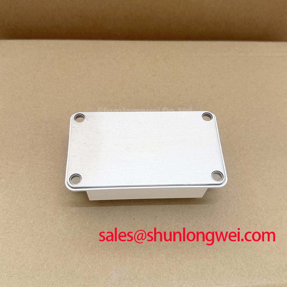
Mounting quality determines whether the tested electrical condition can be reproduced under load. Clean the mating surfaces and use the approved thermal interface material as directed by the original equipment or module documentation. Design Consideration: apply thermal material uniformly enough to fill surface irregularities without creating an unnecessarily thick thermal barrier, tighten fasteners in the prescribed pattern, and use the specified torque for the exact hardware. Do not transfer a generic torque value to this Semitrans assembly without verifying the module and heatsink documentation. For a separate power-stage reference used in related converter work, see SKM100GB063D; its presence in another topology does not establish compatibility with this 300.0 A module.