


Content last revised on February 1, 2026
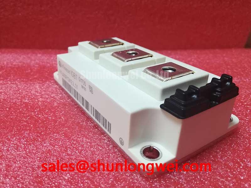
Infineon FF400R12KE3 IGBT Module: Engineering for High-Efficiency Power Conversion
An In-Depth Technical Review for System Designers and Procurement Specialists
Executive Summary: Key Specifications and Engineering Value
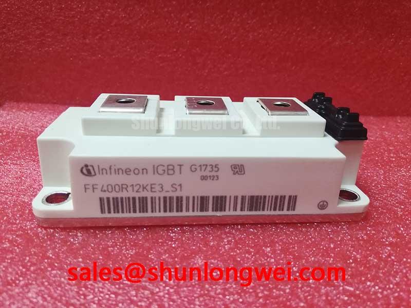
The Infineon FF400R12KE3 is a 1200V, 400A half-bridge IGBT module engineered to deliver a superior balance of conduction and switching performance for high-power inverter and converter applications. This module leverages proven TRENCHSTOP™ IGBT3 technology to provide low conduction losses and robust operation, directly enabling higher system efficiency and enhanced thermal stability. Its core specifications include: 1200V | 400A | VCE(sat) (typ) 1.70V. This translates into tangible engineering benefits such as reduced cooling requirements and improved system reliability. For engineers designing high-power motor drives, the FF400R12KE3 offers a direct path to minimizing power loss without compromising on operational robustness. With its low saturation voltage, this module is an optimal choice for medium-frequency drives where minimizing conduction losses is critical to meeting efficiency targets.
Application Scenarios & Value
Achieving System-Level Benefits in Industrial Drives and Converters
The FF400R12KE3 is engineered for demanding applications where efficiency and reliability are paramount. Its primary value is demonstrated in systems like industrial Variable Frequency Drives (VFDs), servo drives, and Uninterruptible Power Supplies (UPS). Consider a design challenge in a 100 kW VFD controlling a factory automation conveyor system. The engineer's primary constraints are the enclosure size, which limits the heatsink volume, and strict energy efficiency mandates. The FF400R12KE3's typical collector-emitter saturation voltage (VCE(sat)) of just 1.70V at its nominal current becomes a critical design parameter. This low VCE(sat) directly reduces the power lost as heat during the on-state (conduction losses), which is often the dominant loss factor in motor control applications. This reduction in waste heat allows for a smaller, more cost-effective heatsink, enabling a more compact overall system design while still meeting performance targets under demanding industrial conditions. The module's performance is further supported by a maximum operating junction temperature (Tvj op) of 150°C, providing significant thermal headroom for reliable operation during peak load cycles. While this module is ideally suited for 1200V bus applications, for systems requiring higher blocking voltage, the related FZ400R17KE3 offers a 1700V rating in a similar power class.
Key Parameter Overview
Decoding the Specs for Enhanced Efficiency and Thermal Design
The technical specifications of the FF400R12KE3 are centered around delivering efficient and reliable power switching. The following table highlights the key parameters that directly influence system-level performance, from electrical efficiency to thermal management design.
| Parameter | Symbol | Value | Condition | Engineering Significance |
|---|---|---|---|---|
| Collector-Emitter Voltage | VCES | 1200 V | Tvj = 25°C | Defines the maximum blocking voltage capability, suitable for 400V-575V AC line applications. |
| Continuous Collector Current | IC nom | 400 A | TC = 100°C | Specifies the nominal current handling capacity, a primary indicator of power output capability. |
| Collector-Emitter Saturation Voltage | VCE(sat) | 1.70 V (typ) | IC = 400 A, VGE = 15 V, Tvj = 25°C | A critical metric for efficiency. Lower values directly reduce conduction power losses. |
| Gate-Emitter Threshold Voltage | VGE(th) | 5.8 V | IC = 16.0 mA, VCE = VGE, Tvj = 25°C | Determines the turn-on threshold, crucial for gate drive design and noise immunity. |
| Thermal Resistance, Junction to Case | Rth(j-c) | ≤ 0.075 K/W | per IGBT | Indicates the efficiency of heat transfer from the semiconductor to the module baseplate. A lower value simplifies heatsink selection. |
| Short Circuit Withstand Time | tPSC | 10 µs | VGE ≤ 15 V, Tvj = 150°C, VCC = 800 V | Defines the module's robustness against fault conditions, allowing time for protection circuits to react. |
Download the FF400R12KE3 datasheet for detailed specifications and performance curves.
Industry Insights & Strategic Advantage
Leveraging Proven Technology for Cost-Effective, High-Reliability Systems
In an industry focused on maximizing power density and minimizing total cost of ownership, the FF400R12KE3 holds a strategic position. It is built upon Infineon's TRENCHSTOP™ IGBT3 technology, a platform recognized for its maturity and well-balanced performance. While newer technologies like SiC offer lower switching losses at very high frequencies, IGBT3 provides a highly optimized and cost-effective solution for the medium-frequency range (typically 2-15 kHz) common in industrial motor drives and solar inverters. This makes the FF400R12KE3 a pragmatic choice for projects where achieving a specific price-performance ratio is as crucial as hitting efficiency targets. By using this module, designers can avoid the higher component costs and more complex gate drive requirements of wide-bandgap devices while still benefiting from significant efficiency gains over older IGBT generations. This strategic fit ensures that systems built with the FF400R12KE3 are not only efficient but also commercially competitive and built on a foundation of proven field reliability.
Frequently Asked Questions (FAQ)
How does the 1.70V VCE(sat) of the FF400R12KE3 translate to real-world system benefits?
The low VCE(sat) directly reduces conduction power loss (P = VCE(sat) * IC). In a 100 kW inverter operating at 400A, this translates into lower heat generation within the module. This allows for either a smaller, less expensive heatsink for the same operating temperature or, alternatively, running the device cooler with the same heatsink, which significantly improves long-term reliability and the lifetime of the power system.
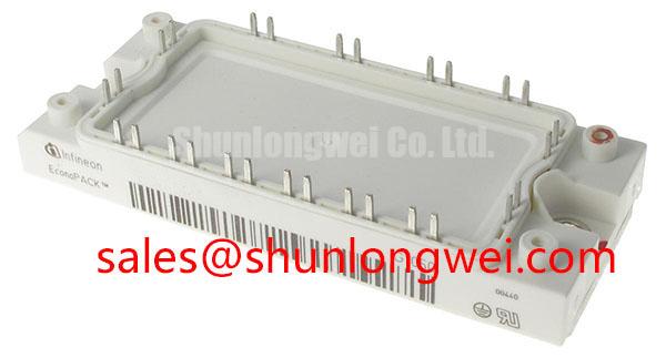
What are the key considerations when designing with the EconoPACK™+ housing?
The EconoPACK™+ is an industry-standard housing known for its reliability. Key design considerations include ensuring proper mounting torque to achieve a low thermal resistance to the heatsink and utilizing the integrated NTC thermistor for accurate temperature monitoring. The screw terminals provide robust electrical connections, but busbar design should be optimized to minimize stray inductance, especially in applications pushing higher switching speeds.
For what range of switching frequencies is the TRENCHSTOP™ IGBT3 technology in this module best suited?
TRENCHSTOP™ IGBT3 technology is engineered to offer an excellent trade-off between conduction losses (VCE(sat)) and switching losses (Eon, Eoff). This makes the FF400R12KE3 ideal for applications operating in the typical industrial frequency range of approximately 2 kHz to 15 kHz. Within this range, it provides a highly efficient solution that balances performance, thermal load, and system cost effectively. For a deeper understanding of this balance, refer to our guide on IGBT selection for high-frequency designs.
The FF400R12KE3 stands as a robust and efficient component, providing a solid engineering foundation for the next generation of industrial power conversion systems. Its design prioritizes the key metrics that allow for the development of reliable, power-dense, and commercially viable products that align with modern energy efficiency standards.