







Content last revised on September 25, 2026
SKN 26/12 Thermal Electrical Optimization: Semiconductor Protection Fuse Selection in Practical Tuning
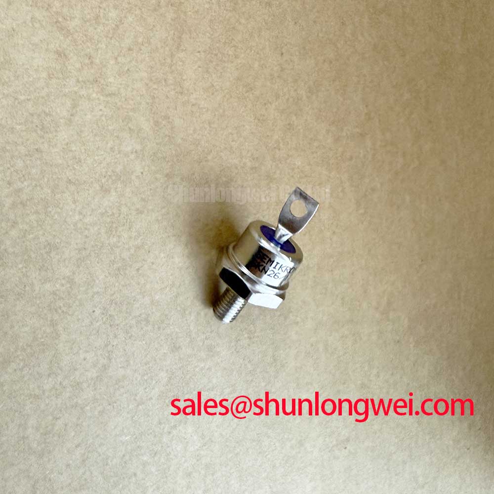
Begin a replacement check by isolating the rectifier, recording the nameplate data, inspecting the stud and terminal surfaces, and confirming that the installed part is specified for the circuit position. The Semikron SKN 26/12 is a discrete power diode with an official repetitive peak reverse voltage of 1200 V and an average forward current of 26 A at Tc = 100°C. Its official surge forward current is 375 A for 10 ms at 25°C, while the maximum forward voltage is 1.55 V at IF = 60 A.
For a high current green hydrogen electrolyzer DC power rectifier, semiconductor fuse coordination must be verified against the actual fault current, prospective short circuit current, clearing time, and the diode manufacturer’s permissible surge and I2t data. The supplied product information confirms the SKN 26/12 surge current rating, but it does not establish a universal fuse I2t coordination value. Designers should therefore obtain the applicable fuse coordination table and compare its clearing energy with the complete diode withstand data before approving a protection scheme.
During maintenance, inspect the fuse holder, busbar contact area, and terminal connection for heat discoloration or looseness. A fuse that clears correctly can still leave evidence of excessive connection resistance elsewhere in the current path. The SKN 26/12 should be assessed together with the protection device, busbar geometry, cooling arrangement, and measured current waveform rather than treated as an isolated fault-clearing solution.
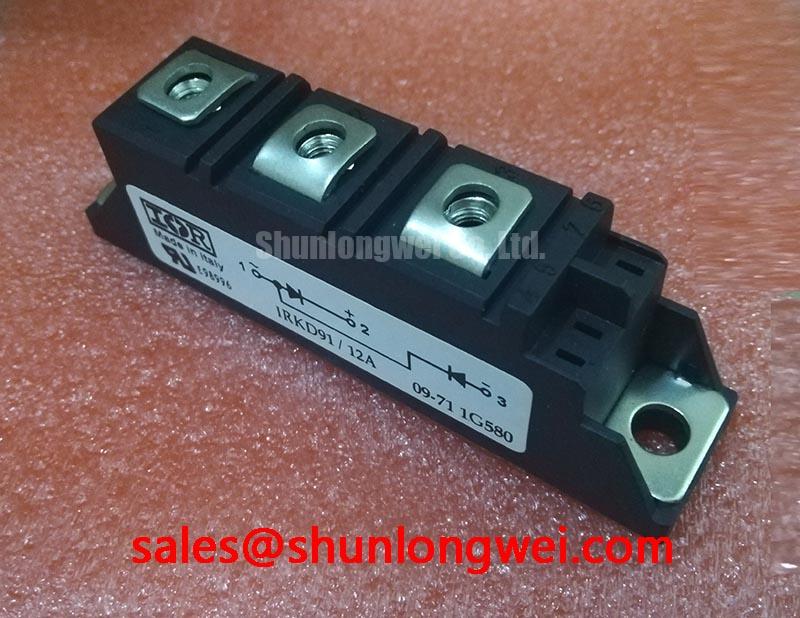
For a neutral replacement review, engineers may also compare the circuit position, electrical ratings, mechanical envelope, and thermal interface requirements with the SKT340/18E thyristor. This is a compatibility reference only, not an indication of interchangeability; the system designer must verify terminal arrangement, reverse-voltage duty, current sharing, control requirements, and the original equipment documentation before selecting any alternative device.
Assembly Integrity and Layout Architecture: Implementing Thermal Avalanche Margins during High Peak for SKN 26/12
The official 375 A, 10 ms surge forward current rating at 25°C is a defined test condition, not a continuous operating target. In a six-pulse or twelve-pulse rectifier, the engineer should compare measured half-cycle current, ambient temperature, heatsink temperature, repetition pattern, and reverse-voltage reapplication against the complete manufacturer data. The phrase “thermal avalanche margin” should not be used as a substitute for a verified transient test, because the available product parameters do not by themselves define the permissible repetitive overload profile.
Transient thermal impedance, commonly identified as Zth, should be evaluated from the applicable datasheet curve when short current pulses produce a meaningful junction temperature rise. The calculation belongs to the complete thermal network, including the diode junction, case interface, heatsink, airflow, and enclosure. System engineers should verify peak junction temperature and reverse-voltage margin with instrumented switching tests before releasing the rectifier for service.
Industrial drive boards controlling the rectifier may use an optocoupler or digital isolator. Common-mode transient immunity is a property of that isolation interface and its layout, not an SKN 26/12 diode rating. Keep the high-current commutation loop physically controlled, separate sensitive control wiring from busbar transitions, and validate the gate or firing signal path with an oscilloscope. Negative-bias gate-drive guidance is relevant to controlled switching devices rather than this diode, but the system-level discussion is available in Evolution of Negative Off-Bias Gate Drive Circuits.
Maintenance Note: De-energize and discharge the rectifier assembly before touching terminals, then monitor contact temperature and check heatsink airflow during scheduled inspections.
Assembly Integrity and Layout Architecture: Implementing High Current DC Rectifier Topologies for SKN 26/12
The SKN 26/12 can be evaluated in industrial diode bridge positions where its 1200 V reverse-voltage rating and 26 A average forward-current rating at Tc = 100°C match the electrical and thermal conditions established by the equipment designer. A six-pulse bridge normally uses three phase legs and produces the primary rectified DC waveform. A twelve-pulse arrangement uses phase-shifted secondary supplies and two bridge groups to reduce selected line-current harmonics, subject to transformer and system design.
At kiloampere-level DC output, multiple current paths may be required. Current sharing depends on transformer impedance, busbar symmetry, diode forward-voltage variation, thermal balance, and the resistance and inductance of each path. The SKN 26/12’s maximum forward voltage of 1.55 V at 60 A can be used as an official reference point for loss assessment, but it is not a complete prediction of assembly loss at every operating current or temperature.
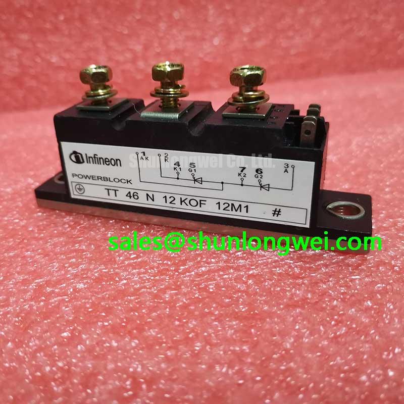
An interphase transformer may be used where the topology requires current balancing between bridge groups. Its impedance, insulation system, cooling, and connection sequence must be verified against the original rectifier design. The related SKT240/18E thyristor may be reviewed only as a separate controlled-device reference, not as a drop-in substitute for the SKN 26/12; voltage, current, mechanical, control, and thermal compatibility must be confirmed before any procurement decision.
Protection studies should include the actual DC-link capacitance, transformer fault contribution, semiconductor fuse behavior, and measured commutation overlap. Neither the diode nor a discrete power device can independently claim compliance with complete EMC requirements such as CISPR or EN 55011; those assessments apply to the finished equipment and installation.
Assembly Integrity and Layout Architecture: Implementing Thermal Interface Material Spreading across SKN 26/12
The SKN 26/12 uses an M6 threaded stud for mounting. The final assembly should provide a clean, flat heatsink contact surface, uniform clamping, and a thermal interface layer applied according to the selected compound manufacturer’s instructions. The official operating junction-temperature range is −40°C to +180°C, but this range does not remove the need to calculate the junction temperature from measured case temperature, forward loss, interface resistance, and heatsink performance.
Do not infer the product’s thermal resistance from the stud size or from a generic mounting practice. The applicable Rth(j-c) value, if required for the design, must be taken from the relevant Semikron documentation for the exact construction and mounting condition. After assembly, inspect the contact pattern, check that the diode body is not mechanically distorted, and repeat temperature measurements under representative current.
Preventive maintenance should include heatsink dust removal, inspection for aged or displaced thermal compound, terminal torque verification against the manufacturer’s mechanical instructions, and checks for condensation in low-temperature or humid enclosures. HALT and HASS methods described in Highly Accelerated Life Testing and Stress Screening can inform a broader equipment qualification plan, but they do not provide SKN 26/12 lifetime figures. Likewise, Negative-Bias Temperature Instability concerns gate-dielectric behavior in controlled semiconductor structures and should not be presented as an SKN 26/12 diode rating.