Content last revised on October 10, 2026
Parallel Digital Signal Reflections Mitigation via Series Damping Termination Resistors
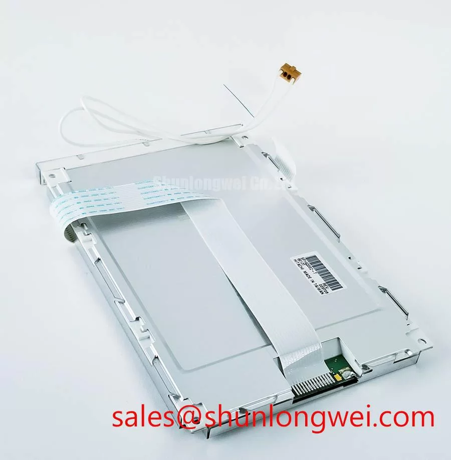
| Model | SP14Q006-TZA |
| Manufacturer | KOE / Hitachi |
| Product Category | Industrial Grade LCD/HMI Panel |
| Display Technology | FSTN / STN Monochrome Passive Matrix LCD Panel |
| Specification Status | Decoded Baseline / Standard Form Factor |
| Electrical Ratings and Resolution | Consult the applicable panel documentation before integration |
Check the original controller waveform at the panel interface before changing termination components, with particular attention to frame synchronization, line pulse activity, and dot clock timing. The SP14Q006-TZA is identified as an FSTN/STN monochrome passive matrix LCD panel, so its interface should be evaluated from the host controller documentation rather than treated like a modern TFT LVDS display.
When the original assembly uses parallel digital control lines, excessive edge ringing can shift the apparent timing of frame and line transitions. A series damping resistor is a Design Consideration, not an official specification of this panel. Its value and placement must be selected from the controller output impedance, cable length, connector structure, and measured waveform. Place the component close to the active driver when bench testing, then compare the signal at the panel connector with a known-good assembly.
Power-up order also matters. The controller should establish the required logic conditions before applying the panel bias sequence defined by the original equipment. Applying a bias rail while control inputs are floating can create abnormal electro-optical behavior or leave the display in an apparently locked state. Any claimed FLM, LP, CP, or bias timing must be checked against the original documentation for the exact equipment revision.
For service work, separate a contrast problem from a digital timing problem. A stable but incorrectly timed frame signal can produce missing rows or unstable characters, while a poor bias supply can produce broad contrast washout. The practical measurement is a synchronized oscilloscope comparison of the control lines, supply rails, and visible display response. Do not transfer LVDS assumptions to this passive matrix panel without confirming the host interface.
Engineers working on a mixed-generation HMI platform can use The Ultimate Guide to Industrial TFT LCD Technology as a technical reference for contrasting TFT timing, signal integrity, and passive matrix integration requirements.
CCFL Inverter Strike Failure Localization: Differential Tube Aging vs. Ballast Transistor Breakdown
Isolate the backlight circuit from the LCD signal path before diagnosing a dark panel, because a failed illumination system can be mistaken for a defective display matrix. The supplied product identity confirms the LCD panel technology but does not establish a CCFL assembly, tube current, inverter strike voltage, or ballast topology as an official specification for this model.
If the surrounding equipment uses a legacy CCFL backlight, treat the inverter output as a hazardous high-voltage circuit and follow the original service documentation for probe selection, insulation, clearance, and discharge procedure. The proposed ignition and operating values sometimes associated with CCFL systems must not be assigned to the SP14Q006-TZA without a source tied to the actual backlight assembly.
Differentiate tube aging from inverter transistor failure by observing the start sequence, transformer output behavior, protection shutdown, and current-sense response. A brief flash followed by shutdown can involve the tube, transformer, wiring, lamp connector, or inverter protection circuit; it is not a single-cause diagnosis. Inspect the connector for carbon tracking, looseness, and contamination, then compare both lamp branches where the equipment design provides access.
High-voltage routing is a system-level safety and EMC issue. Keep the lamp wiring away from sensitive logic conductors, preserve the original insulation arrangement, and inspect transformer potting or encapsulation for visible cracking. Corona suppression, creepage, and clearance must follow the inverter assembly design and applicable safety requirements rather than a generic value copied from another display family.
For a marine radar or navigation console, salt contamination around the inverter and lamp connectors deserves particular attention. A clean-looking LCD face does not confirm that the backlight compartment is electrically sound. Use an approved cleaning process and allow the assembly to dry fully before energizing it.
Cold-Start Response Time Viscosity Damping across Sub-Zero Machine Environments
Compare the panel response during a cold start with the response after the enclosure reaches its normal operating condition, watching for slow contrast recovery, uneven characters, or delayed illumination. These symptoms can involve the LCD cell, bias generation, connector contact, or backlight system, and should be documented against the equipment temperature rather than assigned to one internal material or mechanism.
The FSTN/STN monochrome passive matrix construction should be assessed according to the environmental limits specified for the complete panel assembly. Do not infer a temperature range, liquid-crystal viscosity curve, polarizer composition, adhesive formulation, or cold-start time from the model code. If a legacy terminal has spent years in sunlight, inspect the viewing surface for haze, bubbling, delamination, and localized contrast loss while checking whether the symptom follows temperature or illumination.
High ambient light can make a functioning monochrome display appear weak. Evaluate the optical stack with the equipment visor, cover glass, and ambient lighting in their normal positions. Anti-glare or anti-reflective treatment should be confirmed from the original panel construction; it should not be assumed solely because the display is intended for industrial equipment. The NTSC Color Space Standard is relevant to color-gamut discussions, but it is not a performance specification for this monochrome panel.
For a harsh marine radar or navigation bridge console, enclosure sealing, salt exposure, heater operation, and condensation control belong to the system integration review. When the panel is removed, record the cable orientation and connector seating before disturbing the assembly. A replacement should be compared for viewing direction, mechanical envelope, interface wiring, and backlight arrangement, not only for nominal diagonal size.
Negative Bias Rail Generation and Thermal Contrast Drift Compensation
Measure the panel bias rails at the connector during startup and steady operation while observing the contrast control, because a drifting negative rail can affect the entire character field rather than one isolated segment. The commonly cited negative-bias ranges and ripple limits in generic STN service notes are not official specifications for the SP14Q006-TZA and must not be presented as acceptance limits for this model.
Use the original controller schematic to identify the roles of VEE, V0, contrast adjustment, and temperature compensation. Check ripple under the actual display load, then compare the rail with the controller reference and the visible contrast. A rail that changes with enclosure temperature may point toward the regulator, compensation network, connector resistance, or power distribution rather than the LCD cell itself.
Thermistor compensation is a Design Consideration for equipment that must remain readable across a wide temperature range. Its curve, placement, and adjustment are determined by the host circuit. Do not substitute a generic thermistor value or force a fixed contrast setting until the original control scheme has been identified.
Elastomeric zebra connectors, if present in the equipment assembly, require even compression across the contact area. Inspect for contamination, uneven seating, compression marks, and oxidation on accessible contact surfaces. Anhydrous isopropyl alcohol may be considered for compatible external contacts, but the cleaning method must suit the connector materials and equipment service instructions.
Field Alert: Disconnect power and allow stored energy to discharge before inserting or removing the panel cable, because contact transients can damage the controller interface.
When the display is restored, verify the complete chain: controller timing, bias stability, contrast across temperature, backlight behavior, cable retention, and mechanical pressure on the panel. This sequence is especially important when evaluating the part for industrial HMI consoles, CNC operator panels, or marine navigation equipment where the surrounding system can influence the apparent display fault.