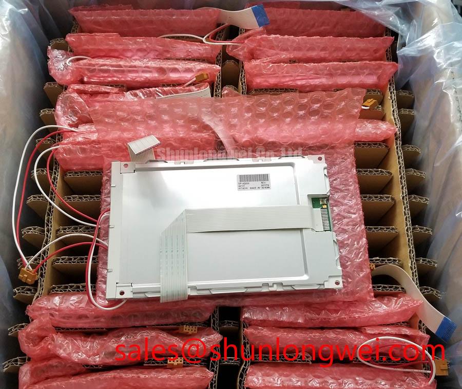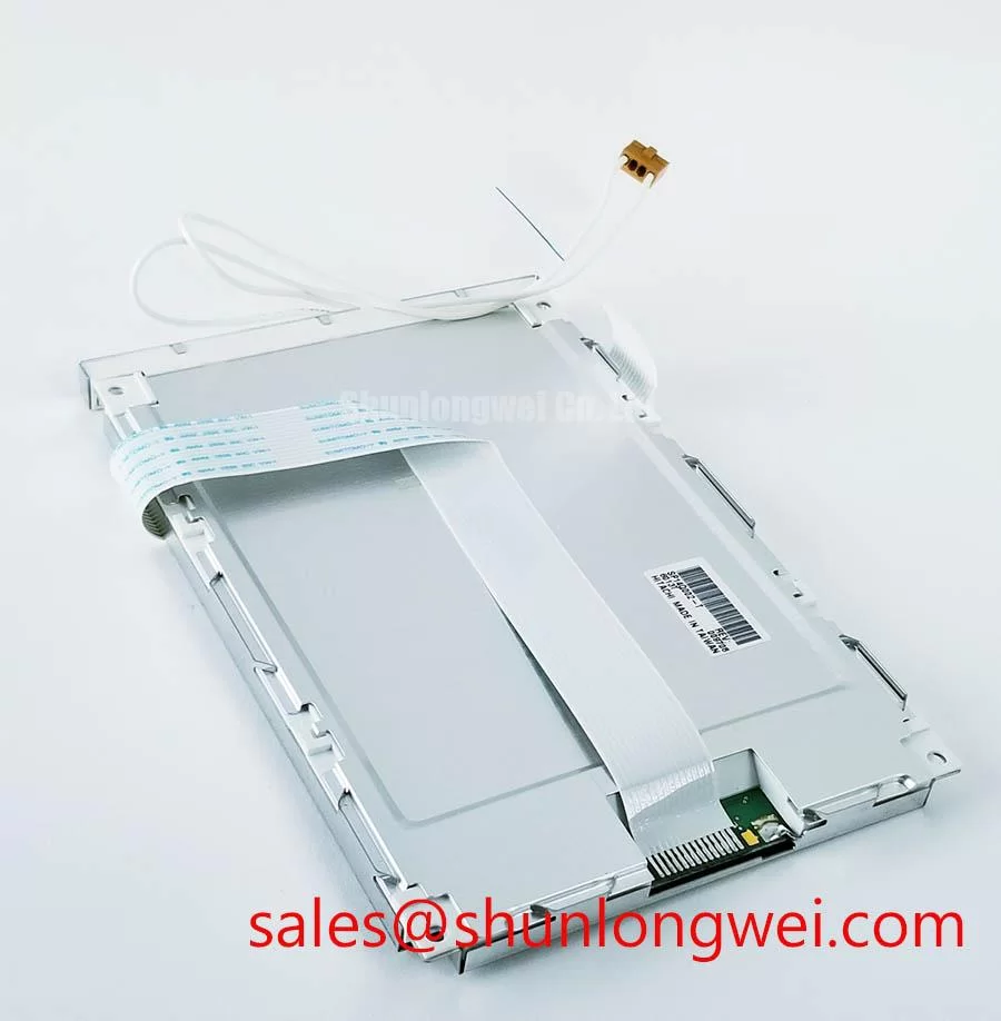



Content last revised on September 12, 2026
Dynamic Contrast and Temperature-Dependent Optical Behavior
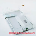
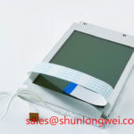
Inspect the SP14Q006-T on a controlled bench using full white, full black, red, green, blue, and mid gray test fields. These patterns make isolated pixel irregularities, broad luminance nonuniformity, color imbalance, and edge effects easier to observe than a normal application screen. Record observations by screen zone rather than assigning a single cause to a visible defect. A dark field issue, for example, can involve the display assembly, optical stack, input signal, cable seating, or the host backlight control path.
Liquid crystal behavior is temperature dependent, so a panel evaluated immediately after removal from a cold cabinet or an unconditioned workshop may not match its stabilized appearance. Design Consideration: allow the display and the known good reference path to reach the same practical test condition before comparing grayscale transitions, contrast perception, or response behavior. Do not treat a broad viewing angle, panel mode, anti glare treatment, contrast ratio, brightness, or operating temperature range as an SP14Q006-T factory specification unless those items are confirmed in the original KOE / Hitachi documentation.
Where the host system controls display illumination through PWM, verify the waveform and its interaction with the original panel assembly using suitable measurement equipment. Audible behavior, visual flicker, or nonlinear perceived brightness can arise from the wider display and controller combination, rather than from one isolated part. The panel documentation should govern the permitted backlight drive method and connection arrangement.
Bench Tip: Keep the unit and test cable within an ESD controlled work area, then insert the flex or harness squarely and confirm its lock is fully engaged before applying power.
Display Interface Synchronization & Logic Power Rail Verification
Before connecting the SP14Q006-T to a replacement controller or an industrial machine, identify the original display interface from the equipment schematic, panel documentation, or a verified cable assembly. The supplied factory record does not establish whether this specific model uses TTL digital RGB, LVDS, a particular bit depth, a particular data mapping, or a defined logic supply voltage. The system integrator should verify the required supply voltage from the original panel documentation.
Check that the host power sequencing and video timing follow the panel manufacturer’s requirements. Split images, unstable colors, repeating vertical areas, or a blank illuminated screen may indicate an interface mapping, timing, signal integrity, or connector seating concern. They should be investigated by comparing the signal path with a known good system or validated schematic, rather than by assigning the symptom to a single failure mechanism.
Engineering Recommendation: preserve the original routing discipline and shield termination strategy when servicing the display cable. This helps maintain the signal conditions established by the equipment designer. For background on how frequency response and phase behavior are evaluated in electronic systems, see the external technical reference on Bode plot frequency response and gain/phase margin. It is contextual information for host electronics evaluation, not a display certification or an SP14Q006-T factory specification.
At low ambient temperature, observed image transition behavior can differ from room temperature behavior. When the machine incorporates environmental conditioning or a heater arrangement, verify that control method against the original equipment documentation. Do not add or alter heater control based on generic display assumptions.
Radiated Emissions Evaluation and Backplate Grounding
When an SP14Q006-T is assessed in a CNC operator panel or robot teach pendant, treat the display, cable, controller, enclosure, and nearby drive equipment as one installed system. Image jitter or horizontal noise bands appearing near motor drive activity may be associated with cable shielding, bonding continuity, controller grounding, power quality, routing, or the operating condition of adjacent equipment. Check each interface objectively, beginning with connector retention, cable damage, shield continuity where applicable, and the host enclosure’s intended bonding points.
Design Consideration: retain the equipment manufacturer’s shield termination and chassis grounding approach when replacing a display module. Changes to cable length, shield connection, ferrite placement, or chassis contact can alter the behavior of the complete installation. The SP14Q006-T is a display module; no claim is made that it independently meets CISPR Class A, CISPR Class B, or any system level EMC requirement. Compliance must be evaluated on the completed equipment configuration.
If service engineering requires an alternative panel assessment, the mechanically and electrically relevant documentation must be compared line by line. The linked TX23D11VM2BAA can be reviewed as a direct replacement candidate only after the original interface, mechanical envelope, optical requirements, and host timing are verified. It is not a blanket substitute recommendation.
For teams establishing a repeatable display intake procedure, The Ultimate Guide to Industrial TFT LCD Technology provides supporting context on panel selection principles and common integration checks. Use the original model documentation as the controlling source for this particular module.
Preventing Localized Optical Nonuniformity from Mechanical Loading
Before final assembly, position the SP14Q006-T in the original bezel without forcing the corners or imposing load through the viewing area. With the panel powered on under a dark field and a uniform light field, inspect the screen after each stage of enclosure closure. Localized bright or dark areas can become easier to see after mechanical loading, but diagnosis should also include the front bezel, support surfaces, cable routing, display alignment, and any material between the enclosure and module.
Engineering Recommendation: use the original equipment manufacturer’s mounting sequence, hardware, torque specification, and support geometry. The supplied factory data does not provide an authorized fastener torque, bezel tolerance, sunlight readability figure, anti glare specification, contrast figure, light guide construction, or compression limit for the SP14Q006-T. Applying generic torque values as if they were product specifications could damage the module or obscure the actual assembly issue.
For installation in a CNC operator panel or robot teach pendant, confirm that the display remains free of cable strain after the enclosure is closed and during normal equipment movement. Inspect for pressure transfer from retaining clips, gaskets, touch overlays, or front covers. A final full screen color and grayscale check after reassembly gives service personnel a documented basis for deciding whether the optical appearance and signal presentation remain consistent with the repaired equipment.