Content last revised on October 5, 2026
Dynamic Contrast Ratio Stabilization and Liquid Crystal Temperature Tracking
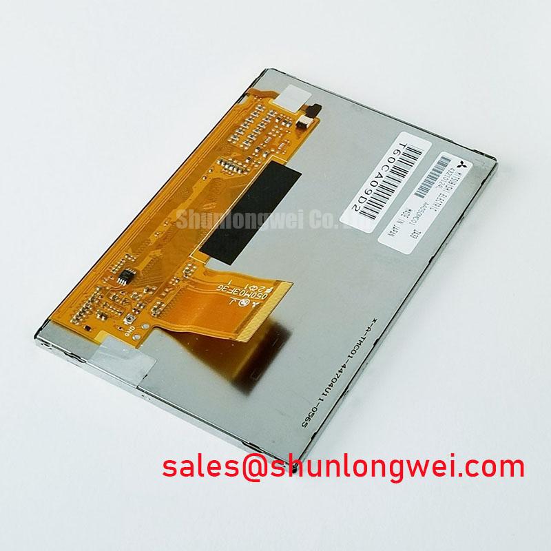
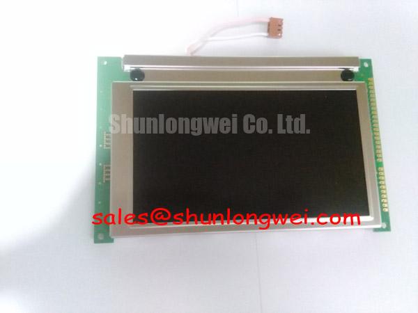
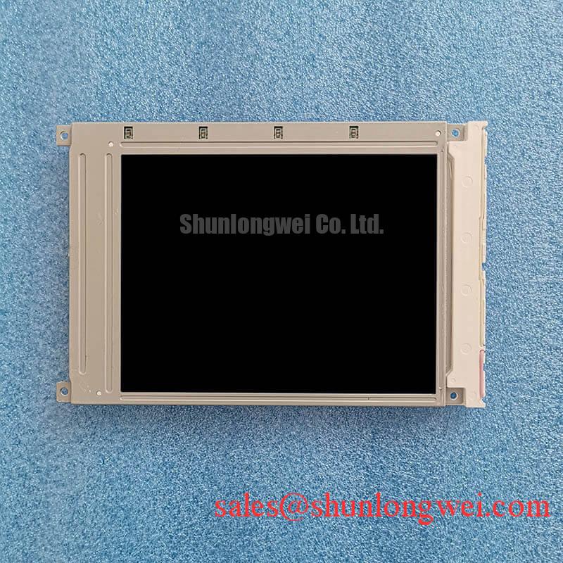
Begin the replacement check by isolating power, inspecting the display frame and connector area, and comparing the panel marking with AT050TN22-V1 before removing the existing module. The supplied factory information identifies this unit as an Ampire Industrial Grade LCD/HMI Panel in a TFT-LCD Display Module form factor. Interface pinout, supply voltage, optical dimensions, backlight drive details, and environmental ratings should be confirmed against the original panel documentation before installation.
For a railway passenger information system or cab signalling display, the first practical evaluation is not a contrast-ratio claim but image stability under the actual enclosure lighting and temperature conditions. The AT050TN22-V1 is identified in the supplied factory data as a TFT-LCD display module, while no verified viewing-angle, contrast-ratio, response-time, anti-glare, or anti-reflective surface figures are provided here. Those values should not be assumed from the model number.
TN, IPS, and MVA panels can produce different grayscale behaviour as the viewing direction, ambient temperature, and drive waveform change. A replacement assessment should therefore compare the unit with the known-good display at the same brightness setting and from the intended operator position. Check dark grayscale steps, mid-tone uniformity, and text edges rather than relying only on a white-screen test. If the image changes significantly when viewed from above or below, the system integrator should verify whether the original equipment requires a particular panel technology or viewing-angle specification.
Cold operation requires careful observation of motion rendering. Liquid-crystal viscosity generally changes with temperature, so grey-to-grey transitions may become visibly slower in a cold cabinet. This is a Design Consideration, not an AT050TN22-V1 factory performance guarantee. If a heater strip, cabinet heater, or controlled warm-up sequence is used, its operation should be evaluated with the complete enclosure, including condensation control and airflow. The display should reach the equipment manufacturer’s permitted operating condition before demanding rapid screen updates or alarm animations.
High ambient illumination also changes the service diagnosis. Reflections from a protective window can be mistaken for poor black level, while surface contamination can create uneven bright areas. Clean the viewing window with a process approved for the enclosure material, then inspect the display using the same incident light direction found in service. AG or AR treatment must be confirmed from the original panel documentation; it is not stated in the supplied AT050TN22-V1 data.
For extended technical background on TFT selection, operating principles, and common selection errors, engineers can refer to The Ultimate Guide to Industrial TFT LCD Technology. The article should support the application review, but it does not replace the original panel drawing or equipment service manual.
Radiated Emissions Assessment Around Variable Frequency Drives
Display faults appearing near servo amplifiers or variable frequency motor drives require a system-level investigation. Pixel jitter, intermittent horizontal noise, or unstable image updates can involve cable routing, shield termination, controller timing, grounding, power conversion, or the display itself. The AT050TN22-V1 factory data supplied for this page does not state an EMC class, CISPR compliance status, LVDS pinout, TTL compatibility, cable construction, or differential impedance.
A practical test begins with the display operating from the original controller and cable assembly. Record the symptom while the nearby drive is idle, accelerating, decelerating, and operating at its normal switching pattern. Repeat the test with the display cable routed as in the machine and then compare it with a controlled temporary routing arrangement. This comparison can indicate coupling sensitivity without assigning a single cause prematurely.
Where the interface is a differential link, the system designer should verify the required characteristic impedance from the controller and panel documentation. A commonly used LVDS design consideration is a controlled differential path around 100 Ω, but this is not an official AT050TN22-V1 specification unless confirmed by the applicable datasheet. Pair symmetry, connector construction, shield bonding, and return-current continuity should be checked together. Measuring the known-good signal path with suitable high-bandwidth probing can help identify reflections, excessive common-mode movement, or timing margin problems.
Backplate grounding should be treated as an installation decision rather than a guaranteed feature of the module. A low-impedance, mechanically secure shield connection can reduce unwanted coupling when it is compatible with the equipment’s grounding architecture. Engineers should avoid creating multiple uncontrolled return paths through mounting hardware, cable shields, and signal reference conductors. Any ferrite or common-mode suppression component should be selected and validated against the actual data rate, cable length, and signal waveform, because an unsuitable part can affect edge quality as well as noise.
The display module itself cannot be described as independently certified to CISPR Class A or Class B. Compliance belongs to the completed equipment and its installation. A railway cab or passenger information system should be tested in its final mechanical arrangement, with the specified controller, cable routing, enclosure, power supply, and nearby traction or auxiliary equipment present.
Backlight Drive Verification, Dimming Behaviour, and Fault Isolation
The supplied official information classifies AT050TN22-V1 as a TFT-LCD display module but does not confirm whether the particular assembly uses an LED or another backlight arrangement, nor does it provide a backlight current, forward-voltage range, PWM ratio, half-life value, or protection threshold. The system integrator should verify the required backlight supply and control method from the original panel documentation rather than applying a generic LED or CCFL assumption.
When a screen appears dark, first determine whether the image data is still present. A faint picture visible under controlled illumination can suggest that the image-generation path is active while the backlight path requires further examination, but this observation is not a conclusive component diagnosis. Check the controller status, display enable signal, backlight command, supply presence, connector seating, and protective circuitry according to the equipment schematic. Do not probe an unknown backlight connector as though it were a low-voltage logic header.
For an LED-backlit assembly, an open string, connector resistance, driver shutdown, or current regulation fault can produce similar field symptoms. For a cold-cathode design, the inverter and lamp circuit require a different safety procedure. Since the supplied AT050TN22-V1 data does not identify the backlight architecture, the replacement process should preserve the original approved driver and wiring until the panel documentation confirms compatibility.
Dimming must also be assessed with the host controller. Changes in brightness may be controlled by PWM, analogue level, serial commands, or a dedicated enable input. A specification such as 1000:1 PWM dimming must not be assigned to this model without a source. Engineers evaluating flicker should use the actual camera-sensitive or operator-sensitive brightness range and compare it with the known-good assembly. Audible noise, intermittent dimming, or repeated restart behaviour should be recorded alongside supply and control-signal observations.
In high-illumination railway displays, optical performance depends on the complete stack: panel surface, protective window, ambient light, backlight setting, and viewing angle. A brighter setting may improve readability while increasing thermal load or exposing non-uniformity. The correct operating point should be established through equipment testing rather than by transferring a nominal brightness value from another panel.
Mechanical Installation and Glass-Panel Fault Diagnosis
Before mounting AT050TN22-V1, compare the replacement’s mechanical drawing, active area, connector location, mounting points, and bezel clearance with the original unit. The supplied factory parameters do not include outline dimensions, mounting-hole geometry, glass thickness, or allowable fastening load. These details must be confirmed before the panel is placed into a cab console, passenger information housing, or industrial HMI bezel.
Uneven frame pressure can create image non-uniformity, local bright areas, or visible stress patterns. This is a general Design Consideration for LCD installation, not a model-specific failure prediction. Fasteners should be tightened in a balanced sequence using the equipment manufacturer’s mechanical specification. Spacers, gaskets, and sealing surfaces should sit flat without forcing the glass or concentrating pressure at a corner.
The enclosure seal deserves the same attention as the panel itself. Inspect the gasket for compression damage, gaps, contamination, and loss of adhesion. A poorly seated seal can permit dust or moisture entry and can also allow vibration to transfer directly into the display frame. Check the cabinet ventilation path after installation so that heat from the controller, power converter, and backlight driver does not accumulate around the panel.
For a basic bench check, apply a controlled primary-colour sequence using the original display controller: black, white, red, green, and blue. Look for persistent lines, inactive regions, uneven luminance, colour contamination, and changes when the frame is gently observed without applying pressure. A 45-degree flashlight inspection can help reveal surface contamination, reflected damage, or areas where the backlight is not uniform. It cannot by itself prove a driver-bond or glass defect.
If a fault changes when a cable is repositioned, document the condition and inspect the connector, strain relief, and harness routing. If the symptom remains fixed across signal sources and controlled cable checks, compare the panel against the known-good unit using the same controller and power conditions. This process separates installation, signal, and display-side possibilities without relying on an unsupported single-cause diagnosis.
⚠️ Maintenance Note: Inspect the enclosure gasket and cooling path during scheduled service, and disconnect power before removing or reseating the display cable.
Because the supplied factory record confirms the product category and manufacturer but does not publish the complete electrical and mechanical interface data, final acceptance should be based on the original Ampire documentation and the host equipment service specification. The AT050TN22-V1 identity to verify is Ampire, AT050TN22-V1, Industrial Grade LCD/HMI Panel, and TFT-LCD Display Module.