Content last revised on October 12, 2026
Controlled 100-Ohm Differential Impedance Flex Routing to Suppress High-Frequency Jitter
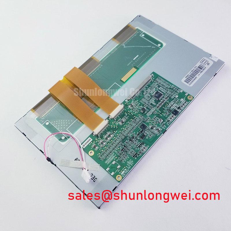
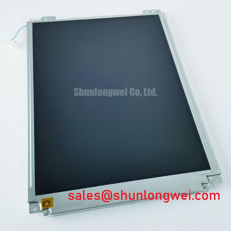
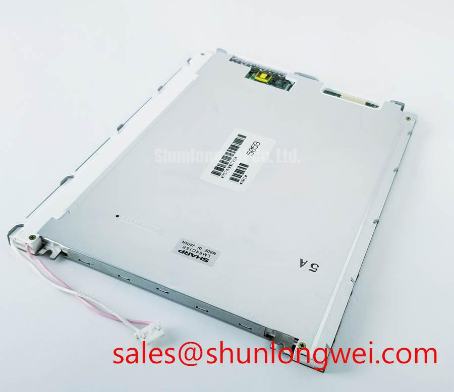
With the panel disconnected from the controller, inspect the FPC and connector seating first, then compare the cold-state display condition with a known-good signal path before applying power. The TP-3142S2 is identified as an AUO Industrial Grade LCD/HMI Panel using a TFT-LCD Active Matrix Color Display Module construction. Its listed configuration is a Decoded Baseline / Standard Form Factor, making interface matching and mechanical verification essential during equipment repair.
For replacement work, the system integrator should verify the original panel documentation for supply requirements, interface protocol, pin assignment, backlight arrangement, mounting geometry, and display timing. The product category alone does not establish a universal voltage, connector map, optical specification, or environmental rating. This discipline is particularly important when evaluating the TP-3142S2 for railway passenger information terminals, cab signalling displays, industrial HMI consoles, or control cabinet monitors.
A practical installation review should also cover gasket compression, bezel flatness, FPC bend radius, connector locking force, and the clearance required for thermal expansion. Uneven frame pressure can create visible mura, local brightness variation, or intermittent electrical contact even when the display electronics remain functional. For broader enclosure, sealing, and industrial HMI integration principles, engineers can consult Industrial Display & HMI Solutions.
Controlled 100-Ohm Differential Impedance Flex Routing to Suppress High-Frequency Jitter
When the host controller uses a high-speed differential display interface, begin by matching the replacement panel’s documented signal mapping rather than assuming that a similar connector provides the same pinout. JEIDA and VESA data arrangements can place color bits and synchronization information differently, producing split-screen images, incorrect colors, or an apparently active panel with unusable graphics.
Design Consideration: a differential routing target of 100 Ω with a tolerance of approximately ±10% and a low pair-to-pair skew budget is commonly used when the controller documentation specifies such an interface. These values are system-level routing objectives, not confirmed factory specifications for the TP-3142S2. The flex cable should be routed away from switching nodes, motor-drive conductors, and high-current return paths. Avoid folding the cable over a sharp chassis edge, because repeated flexing can change conductor geometry and increase intermittent faults.
Power-on behavior should be checked at the panel connector with an oscilloscope. The host designer may evaluate a controlled rise profile, including the stated 0.5 ms to 10 ms engineering window where that requirement belongs to the controller and panel combination. The correct logic supply must come from the original panel documentation; it should not be inferred from the model number. Compare the display enable, clock, and data sequence with the controller’s timing requirements before changing firmware or replacing the panel.
The amorphous silicon TFT technology reference provides useful background on active-matrix display behavior, while the system engineer remains responsible for confirming the electrical interface used by this specific assembly.
Eye-Diagram Voltage Margin & Differential Noise Floor Verification in High-Vibration Bays
Pixel jitter and horizontal noise bands should be evaluated at the receiving panel while the nearby industrial load changes state. A 360-degree shield termination can be considered where the equipment’s EMC architecture supports it, but the shield connection must be planned with the cabinet bonding strategy rather than attached casually at multiple uncontrolled points. Common-mode filtering may also be evaluated by the system designer when measurements show coupling from variable-frequency motor drives.
Use the controller’s reference clock and data timing to inspect eye opening, edge stability, and hold-time behavior across the actual operating temperature range. TTL and LVDS are not interchangeable descriptions: the correct transmitter standard, voltage domain, polarity, and channel order must match the panel interface documentation. If the image becomes unstable only during motor acceleration, compare the panel-side waveform with the controller-side waveform and inspect cable grounding, return continuity, and connector retention.
Vibration introduces a mechanical fault path as well as an electrical one. A connector that appears seated may still experience contact movement if the FPC is unsupported or the bezel applies uneven stress. In railway cab signalling or passenger information equipment, the mounting frame should release local strain instead of transferring it directly to the glass edge. Designers should validate the completed assembly under the equipment’s own vibration profile rather than relying only on a bench image test.
⚠️ Maintenance Note: isolate power before removing or reseating the FPC, and inspect the connector latch and surrounding gasket whenever the panel is serviced.
Managing Motion Response & Image Smearing in Cold-Temperature Industrial Facilities
At sub-zero temperatures, liquid-crystal viscosity can increase and make motion appear slower, especially in scenes with rapid contrast changes. This is a general LCD behavior and should not be presented as a confirmed TP-3142S2 response-time rating. For cold-room, outdoor, or transport equipment evaluations, record image performance during cold start, stabilized operation, and warm-up instead of judging the panel from a single still image.
Gray-to-gray response behavior should be measured using the controller’s normal drive conditions and the intended brightness setting. A change in overdrive or frame timing can alter visual artifacts, but those adjustments belong to the complete display system. If a heater or controlled enclosure is considered, the thermal design must prevent local hot spots, condensation, and abrupt temperature gradients across the glass and bezel.
Perimeter sealing deserves equal attention. A compressed gasket should remain continuous around the opening without wrinkles, gaps, or excessive compression at the corners. The enclosure designer should assess moisture ingress, pressure equalization, and condensation risk during the complete thermal cycle. The TP-3142S2 record supplied for this product does not establish a specific operating temperature range, sealant composition, GTG value, or outdoor qualification, so those conditions must be matched to the original equipment documentation and validated at assembly level.
Backlight Thermal Management & Light Guide Preservation
Backlight replacement work should start by identifying the original optical and electrical arrangement rather than assuming that every TFT-LCD module uses the same light source. The TP-3142S2 is specified here as a TFT-LCD active-matrix color display module, but the provided baseline does not confirm a backlight type, luminance rating, optical material, or LED lifetime value.
Where an edge-lit architecture is documented by the equipment manufacturer, the mechanical design may use an aluminum spreader or equivalent thermal path along the illuminated edge. That is a system-level design consideration intended to reduce localized heating and optical non-uniformity. The spreader must not distort the frame or press directly against sensitive display areas. Thermal contact, airflow, enclosure temperature, and brightness control should be assessed together.
Optical yellowing, uneven brightness, or a darkened perimeter can have several possible causes, including heat exposure, contamination, aging of the light source, or mechanical stress. Inspect the diffuser and guide assembly without introducing fingerprints, cleaning fluid, or abrasive contact. Do not assign a specific L70 or B50 lifetime to this model without a manufacturer-qualified source.
For long-term static HMI screens, application software should use suitable screen-management practices, such as rotating fixed status elements where the equipment permits. This is a system recommendation rather than a confirmed panel protection feature. The mounting bezel should distribute fastening load evenly, while the sealing interface should remain stable through vibration and temperature changes. External technology context can be compared with Tianma industrial TFT-LCD display technologies, but that reference does not define AUO TP-3142S2 specifications.