


Content last revised on September 19, 2026
Preventing Spurious Faults: Short-Circuit Withstand Coordination for ST330C16C0
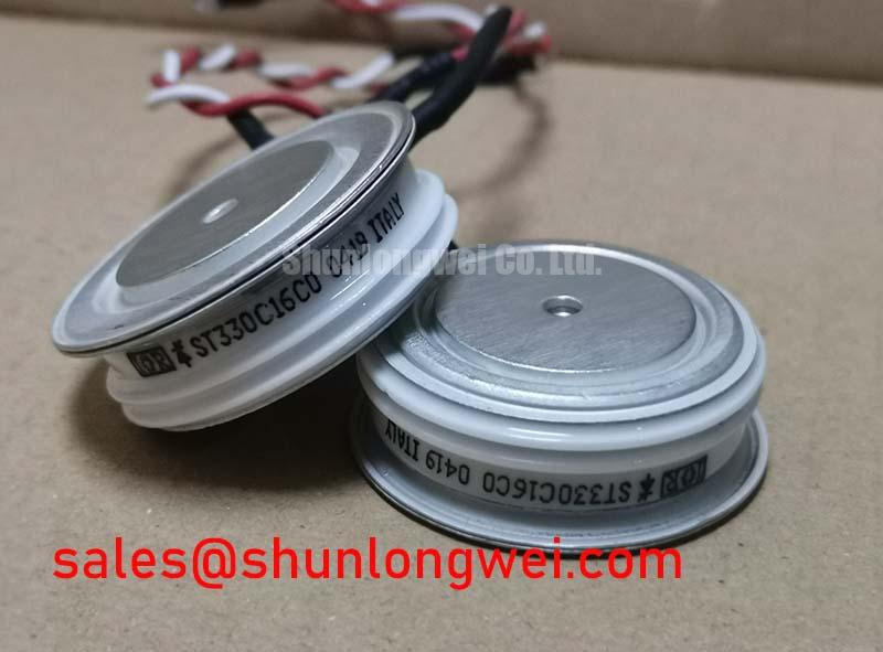
A dead-short fault review should begin with the actual protection documentation, not with a presumed semiconductor fault capability. The available official identification for ST330C16C0 confirms a 1600 V rating and 330 A current rating, but it does not establish a permissible fuse clearing I²t value, surge-current capability, or short-circuit withstand time. Those values must be taken from the applicable manufacturer documentation for the module and the chosen fuse.
For maintenance work on a grid-tied static var compensator or thyristor-switched capacitor bank, compare the fuse manufacturer’s pre-arcing and total-clearing I²t data with the semiconductor protection limits stated for the installed assembly. Check every associated connection in the current path, including line terminals, busbar joints, fuse clips, and heat-sink mounting points. Loose hardware can introduce localized heating and uneven current sharing, while a protection device with unsuitable coordination can allow fault energy to reach the power block before clearing.
| Verification item | Required reference | Purpose |
|---|---|---|
| Module identity | ST330C16C0 nameplate and circuit drawing | Confirms the installed voltage, current, and connection arrangement |
| Fuse coordination | Fuse time-current and I²t documentation | Assesses clearing behavior during prospective faults |
| Mechanical fastening | Manufacturer mechanical drawing | Confirms the correct torque and contact arrangement |
⚠️ Maintenance Note: Monitor terminal temperature rise during normal loading and recheck air passages, contact surfaces, and fastening condition during planned shutdowns.
Assembly Integrity and Layout Architecture: Harmonic Current Injection and Line Filtering for ST330C16C0
In phase-controlled reactive-power equipment, firing angle changes alter the conduction interval and therefore influence reactive demand, displacement power factor, harmonic content, and capacitor-bank switching behavior. These system effects should be evaluated from recorded voltage and current waveforms at the installed operating point rather than inferred solely from the module’s 1600 V and 330 A ratings.
Design Consideration: keep the high-current paths physically direct and mechanically stable so that busbar movement, terminal stress, and shared impedance do not complicate waveform interpretation. The line filter, firing controls, sensing path, and power connections should be reviewed together when unexpected current distortion appears. A current trace that changes after cabinet work may reflect the complete installation, including control timing, capacitor condition, filtering, and connection integrity.
When assessing another high-current Vishay reference such as VS-ST730C18L0, compare the official circuit configuration, voltage rating, current rating, case outline, terminal positions, thermal data, and protection requirements. A higher current figure alone does not establish interchangeability.
Transient Dynamics and Electrical Design: Thermal Interface Material Spreading Across ST330C16C0
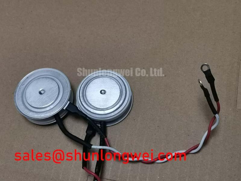
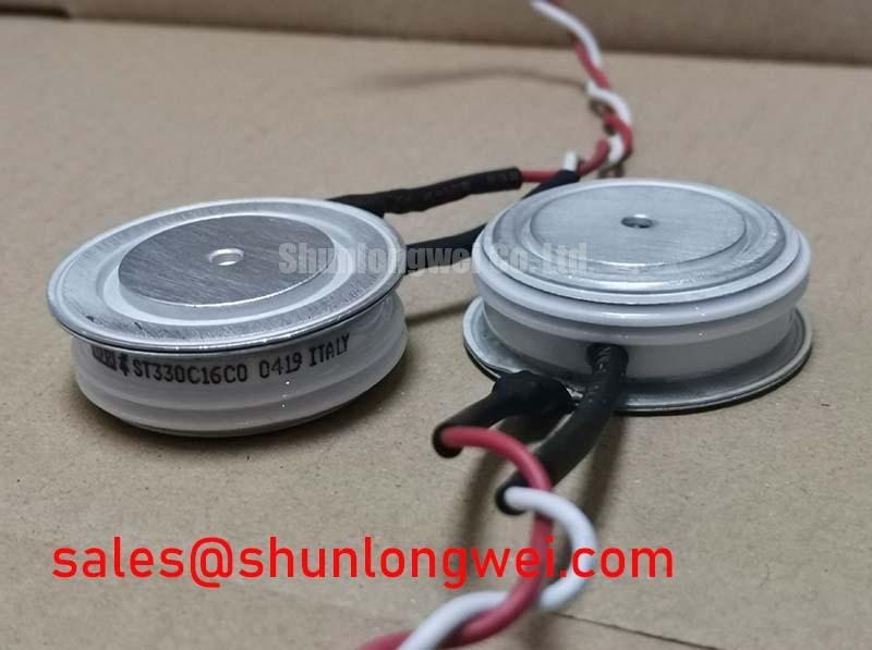
Before reassembly, inspect the mating heat-sink surface for contamination, corrosion, burrs, and evidence of uneven contact. Apply thermal interface material according to the material supplier’s process guidance, then tighten the mounting hardware in the sequence and torque specified by the relevant mechanical documentation. The objective is stable, uniform contact without distorting the Power Block / Bridge Case.
The junction-to-case thermal resistance, transient thermal impedance, and permissible junction temperature must be obtained from the applicable official module documentation before a thermal calculation is accepted. It is not appropriate to assign a thermal resistance value from the package description alone. During commissioning, compare heat-sink temperature behavior and load waveform conditions with the known operating envelope of the equipment. A rising temperature trend can warrant inspection of fan operation, blocked ducts, aged interface material, busbar contact resistance, and the duty cycle imposed by the control system.
Where line-operated converter arrangements are being evaluated, the practical distinction between switching topologies can help frame the test plan. The technical discussion in Resonant Topologies in Home Appliances provides useful context for examining current paths and switching conditions, while the installed ST330C16C0 circuit must still be validated from its own schematic and measured waveforms.
Benchtop Waveform Tuning: Mitigating Stress via Surge Energy Dissipation and Clamping Voltage on ST330C16C0
Before applying power after an outage or retrofit, inspect the surge-protection network, RC snubber components, wiring insulation, and earth-bond continuity. MOV and snubber values cannot be selected from the ST330C16C0 voltage rating alone because their duty depends on the incoming supply, stored energy, cable arrangement, switching sequence, and measured transient behavior. IEC 61000-4-5 can be used as a system-level surge test reference where applicable; it does not certify an individual module as compliant.
Engineering Recommendation: capture line voltage and branch current simultaneously during controlled tests, then verify that transient peaks remain within the limits established by the complete system design and applicable manufacturer data. For fast transient current observation, a properly selected Rogowski coil can provide nonintrusive measurement context; its operating principle is described by Rogowski Coil Principle for Fast Transient Current Sensing. Confirm probe bandwidth, polarity, grounding practice, and the known-good measurement path before acting on a waveform result.

