

Content last revised on September 19, 2026
Polarizer Durability & Optical Retardation Film Inspection under Direct Industrial Lighting
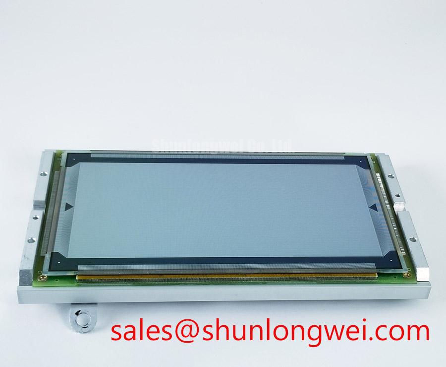
Inspect the powered display from the intended operator position and from off-axis positions under the actual room or task lighting. A polarizer with abrasion, chemical residue, pressure marking, or local delamination can create a contrast change that is easy to miss under dim bench lighting yet disruptive beside direct industrial luminaires. Compare a suspected module with the retained reference display where one is available, using the same source image, brightness setting, and viewing direction.
Do not assign TN, IPS, MVA, anti-glare treatment, viewing-angle performance, or optical-film construction to the EL512.256-H2 unless those details are confirmed by the original Planar documentation. These display technologies have different off-axis grayscale behavior, but their presence cannot be inferred safely from the product designation alone. A practical inspection should instead record what is observable: whether grayscale steps remain distinguishable, whether dark areas shift when the observer moves, and whether reflected lighting obscures critical interface elements.
Cold environments can make a liquid-crystal image appear slower to transition because liquid-crystal viscosity changes with temperature. This is a Design Consideration, not an official operating-temperature specification for this model. Where a cabinet experiences low ambient temperature, service personnel should let the assembly stabilize at its expected operating condition before judging response behavior. If the host equipment includes a controlled heater strip or thermal-management circuit, confirm its control operation from the equipment documentation rather than adding an unverified external heating method.
Surface cleaning should be limited to materials and procedures approved for the installed enclosure and display assembly. Avoid applying local force at the active viewing area while removing residue. Pressure introduced through a bezel, gasket, or cleaning tool can produce temporary or persistent non-uniformity that may be mistaken for an electronic fault.
Preventing Frame Lag & Image Smearing in Cold-Environment & Outdoor Industrial Facilities
When image changes appear delayed in a cold facility, first separate display response from source timing. Hold a static test pattern, then switch to controlled grayscale and full-screen transitions from a known-good video source. If the source signal remains stable while visible transitions slow after ambient temperature falls, the observation can be recorded as temperature-related display behavior. It should not be treated as proof of a failed EL512.256-H2 module without comparison at a stabilized temperature and review of the original system requirements.
The perimeter seal, bezel gasket, and enclosure drainage path deserve equal attention. Condensation can form after a cold assembly is exposed to warmer humid air, while repeated thermal movement can change how an enclosure applies pressure around the display. Design Consideration: distribute mechanical retention evenly around the module and verify that the enclosure gasket contacts the intended sealing surface without pushing on the active display area. The equipment manufacturer determines the applicable environmental limits and sealing arrangement.
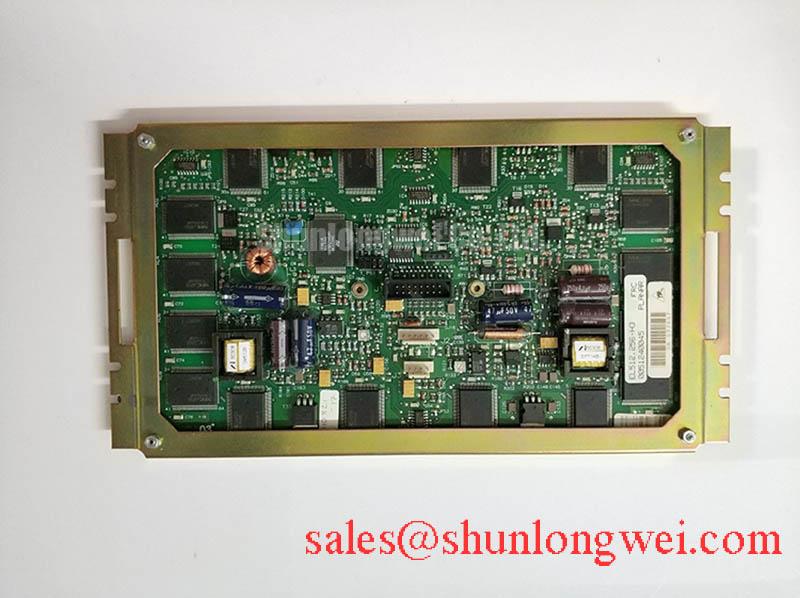
Inspect cable retention before pursuing internal display causes. A cable that is partly released, sharply bent at the connector, or loaded by cabinet vibration can interrupt pixel data or timing even when the panel itself is optically sound. The supplied factory information does not identify the EL512.256-H2 signal interface. For that reason, technicians should identify the original connector, pin assignment, signal standard, power sequence, and host transmitter requirements from the equipment record before testing or replacement.
Clock-jitter and data-hold margins belong to the complete source-to-panel signal path. An oscilloscope measurement at the original connector, compared with a known-good path and interpreted against the relevant interface documentation, can help determine whether frame lag or smearing is associated with transmission integrity. Do not apply generic TTL or LVDS timing limits to this specific module without confirmed interface information.
Eye-Diagram Voltage Margin & Differential Noise Floor Verification in High-Vibration Bays
Start with a visual and mechanical inspection of the connector shell, cable strain relief, chassis bond, and cable route. Horizontal noise bands, intermittent pixel disturbance, or image instability near variable-frequency motor drives can arise from several conditions, including an unstable source signal, poor connector contact, cabinet grounding changes, cable movement, or conducted interference. A scope capture at the source and again at the panel connector provides a more defensible basis for diagnosis than assigning a single cause from the screen symptom.
Where the confirmed original interface uses differential signaling, assess the eye pattern and common-mode behavior against the requirements of the actual host and panel documentation. Shield termination and ferrite use are system-level Design Considerations. Their effectiveness depends on cable construction, enclosure bonding, cable route, grounding architecture, and the noise environment. They should be validated through measurement after installation rather than presented as an inherent property of the EL512.256-H2.
A cable routed beside a motor output cable or drive enclosure may be exposed to a noisier electromagnetic environment than the original installation. Separate signal wiring from known noise sources where the cabinet layout permits, preserve the equipment's intended grounding scheme, and inspect for damaged shielding or strained conductors. The module itself should not be represented as independently certified for complete-system EMC compliance.
Maintenance Note: Isolate equipment power before disconnecting the display cable, then check connector retention, cable shielding continuity, enclosure gaskets, and cooling-air paths before returning the panel to service.
For wider enclosure, sealing, signal-routing, and industrial HMI integration context, consult the Industrial Display & HMI Solutions engineering guide. Test frameworks and terminology should be tied to applicable equipment requirements; the JEDEC standards document library is a useful reference point when evaluating relevant component and test documentation. Partial-discharge methods concern high-voltage insulation systems rather than this LCD module, but the principle of matching a diagnostic method to the actual electrical structure is important when reviewing resources such as partial discharge detection.
Optical Luminance Degradation Curve & CCFL-to-LED Modernization Retrofit Pathways
When a display becomes dim, uneven, flickers, or produces acoustic noise, determine whether the behavior originates in the panel, its illumination assembly, the inverter or driver, the control signal, or the upstream power rail. Use a stable image source and compare the result at the display connector with the known-good service configuration. The supplied official information identifies the EL512.256-H2 as a TFT-LCD display module but does not specify its illumination technology. It is therefore not appropriate to label this exact model as CCFL or LED without the original documentation.
A CCFL-based assembly and an LED-based assembly have different electrical interfaces, control behavior, mechanical stack-up, thermal characteristics, and protection requirements. A retrofit cannot be evaluated solely by whether an image appears on screen. The system integrator should verify the original backlight architecture, mechanical dimensions, illumination control method, supply requirements, connector arrangement, optical uniformity, and safety obligations before considering any modernization work.
Constant-current LED drivers, PWM dimming behavior, and illumination lifetime figures are system and driver dependent. No specific dimming frequency, duty-cycle range, cold-start voltage, or service-life value is claimed here for the EL512.256-H2. Where text flicker or brightness variation is reported, observe the display with a controlled static image and a changing grayscale image, inspect the relevant driver outputs using the service documentation, and compare the panel to an established reference assembly.
For potential use in a high-precision surgical-navigation or ultrasound diagnostic display terminal, the EL512.256-H2 should be assessed as a replacement module against the original equipment documentation. Verify image stability, connector compatibility, enclosure sealing, optical behavior under the intended lighting, and the complete equipment validation requirements before the unit is placed into operational service.