
Content last revised on September 10, 2026
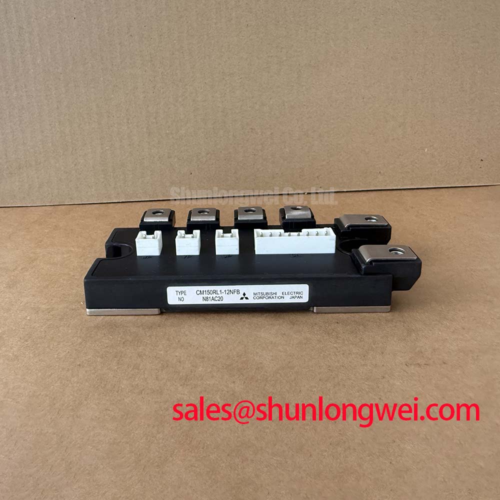
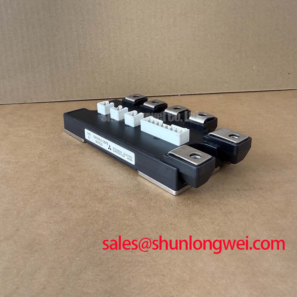
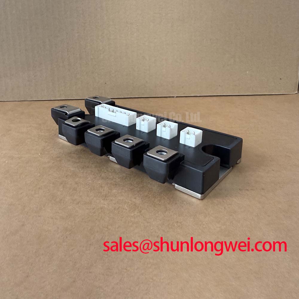
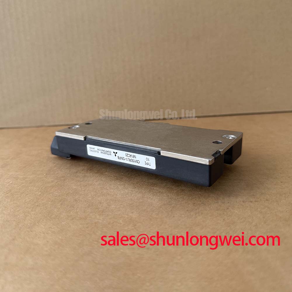
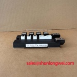
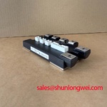
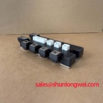
CM150RL1-12NFB Mitsubishi IGBT Module
Product Overview
High-Density Power Control via Integrated CSTBT Technology
The CM150RL1-12NFB is a high-performance 600V 150A 7-pack IGBT module manufactured by Mitsubishi. Designed for efficient power switching, this module integrates a three-phase inverter bridge with an active brake chopper stage. It delivers exceptional efficiency with a low typical collector-emitter saturation voltage (VCE(sat)) of 1.7V.
Key Benefits:
- Minimizes board space and reduces stray inductance in inverter assemblies.
- Enhances reliability through a robust copper baseplate and optimized thermal design.
What is the primary benefit of the 7-pack configuration? It reduces system footprint by integrating inverter and brake chopper stages. How does CSTBT technology lower operational losses? By storing carriers in the drift region, minimizing collector-emitter saturation voltage. For 240V AC motor drives demanding high thermal headroom, this 600V 150A module is the optimal choice.
Application Scenarios & Value
Optimizing Efficiency in Low-Voltage Variable Frequency Drives
Engineers often face design headaches when managing parasitic inductance and thermal packaging constraints in low-voltage industrial systems. The CM150RL1-12NFB resolves these hurdles by providing a single-module solution for 200–240V AC line applications. It is frequently deployed in Variable Frequency Drive (VFD) systems, AC motor drives, and high-capacity Uninterruptible Power Supply (UPS) converters. Designers can consult understanding IGBT modules for a comparative look at topologies.
Consider a factory conveyor belt system experiencing heavy starting currents. A standard discrete configuration is prone to voltage spikes due to stray board inductance. By utilizing this unified 7-pack module, engineers can achieve a tighter layout. This is crucial for securing a robust Short-Circuit Withstand Time during overcurrent spikes. The integrated brake chopper simplifies the connection of dynamic braking resistors, protecting the DC bus during rapid motor deceleration.
While this 600V module is optimized for low-voltage lines, designs requiring higher voltage thresholds may consider the related CM100RL-24NF, which offers a 1200V blocking rating. If a design demands identical electrical characteristics but requires a dual-switch configuration, the CM150DY-12NF represents a suitable option.
Technical & Design Deep Dive
CSTBT Silicon Optimization and Fast-Recovery Diode Performance
At the heart of the CM150RL1-12NFB is Mitsubishi's Carrier Stored Trench Bipolar Transistor (CSTBT™) technology. Traditional planar IGBT structures experience high on-state conduction losses as current ratings increase. CSTBT™ addresses this by creating a carrier-storing layer near the emitter, which significantly lowers the saturation voltage to a typical value of 1.7V at Tj = 125°C. For guidelines on analyzing characteristic curves, refer to decoding IGBT datasheets.
To explain this parameter, think of the saturation voltage as a narrow water valve. When fully open, a narrow valve limits flow and creates friction. A lower VCE(sat) functions as a wide, unrestricted valve, allowing a 150A current to flow with minimal resistance. This reduces the thermal load generated by the device.
Similarly, thermal resistance can be viewed as heat traffic. The module’s low junction-to-case thermal resistance of 0.16 K/W functions like an open multi-lane highway. Rather than letting heat pile up at the silicon junction, the low thermal resistance channels heat rapidly to the heatsink. This keeps junction temperatures well within safe limits. For further layout strategies to maximize cooling, read more about IGBT design and thermal management. The module also integrates a soft-recovery freewheeling diode to suppress high-frequency electromagnetic interference.
Key Parameter Overview
Functional Specs and Electrical Characteristics
| Inverter Section (Tj = 25°C unless noted) | |
|---|---|
| Collector-Emitter Voltage (VCES) | 600V |
| Collector Current (IC) | 150A (continuous at Tc = 97°C) |
| Collector-Emitter Saturation Voltage (VCE(sat)) | 1.7V (typical at Tj = 125°C, VGE = 15V) |
| IGBT Thermal Resistance (Rth(j-c)) | 0.16 K/W (per element) |
| Brake Section (Tj = 25°C unless noted) | |
| Brake Collector-Emitter Voltage (VCES) | 600V |
| Brake Collector Current (IC) | 50A |
| Brake Saturation Voltage (VCE(sat)) | 2.0V (typical) |
| Module Mechanical & Isolation Parameters | |
| Isolation Voltage (Viso) | 2500 Vrms (AC 1 minute) |
| Junction Temperature (Tj) | -40°C to +150°C |
| Weight | ~310g |
Frequently Asked Questions
Addressing Design and Integration Intent
How does the 7-pack configuration of the CM150RL1-12NFB simplify three-phase motor control designs?
By integrating a three-phase bridge (six IGBTs) and a brake chopper into a single package, it replaces multiple discrete components. This simplifies PCB trace routing, reduces parasitics, and minimizes the overall inverter footprint.
How does the low thermal resistance of 0.16 K/W impact heatsink selection in VFD designs?
A low thermal resistance of 0.16 K/W ensures rapid heat transfer from the silicon junction to the baseplate. This allows engineers to use smaller, lighter heatsinks while maintaining stable operating temperatures under continuous switching.
To request a quote, check inventory levels, or speak with an application engineer about your power electronics design, contact our sales team today.