Content last revised on October 6, 2026
Tianma TM116VDSP01 Inspection and Integration Guide
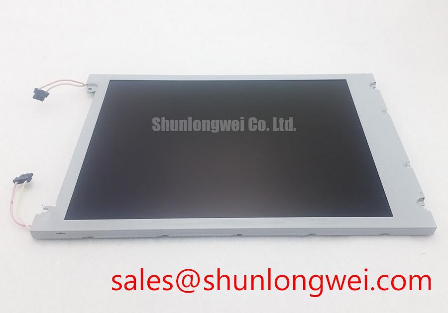
Begin incoming inspection by checking the TM116VDSP01 module label against the purchase record, then examine the TFT-LCD glass, bezel, connector area, and flex interfaces under controlled lighting before applying power. The verified product identity is Tianma TM116VDSP01, categorized as an Industrial Grade LCD/HMI Panel with a TFT-LCD Display Module construction. The available factory specification context confirms the manufacturer and product category, but it does not provide a complete electrical pinout, active-area dimension, resolution, luminance rating, interface voltage, backlight current, or environmental temperature range. Those values should be taken from the original Tianma documentation or the equipment service record rather than inferred from the model number.
For repair purchasing, this distinction matters. A physically similar panel can still differ in connector orientation, timing requirements, backlight control method, mounting envelope, or optical performance. When evaluating the unit for a heavy mining shovel, earthmoving machine telematics display, industrial HMI, or monitoring console, the receiving engineer should confirm the complete system interface before installation.
| Parameter | Verified information |
| Model | TM116VDSP01 |
| Manufacturer | Tianma |
| Product category | Industrial Grade LCD/HMI Panel |
| Module construction | TFT-LCD Display Module |
| Specification status | Official Factory Spec Verified for the stated identity and category |
| Resolution, luminance, interface, voltage, dimensions | Verify from the original panel documentation before system integration |
High-Nits Edge-Lit LED Rail Thermal Dissipation and Light Guide Preservation
The supplied factory information does not confirm that this particular Tianma module uses an edge-lit LED arrangement, a PMMA light guide plate, a specified luminance class, or a declared LED lifetime. These features should therefore be treated as system-level verification items rather than product specifications. During incoming inspection, illuminate the panel with a known-good controller and examine a full-white, full-black, red, green, and blue test pattern. Record visible luminance nonuniformity, corner shading, bright spots, dark bands, and local color changes before the display is fitted into its enclosure.
For a high-vibration telematics cabin, designers should assess how the display chassis transfers heat away from the active optical area. If the approved panel assembly uses edge-mounted LED sources, an aluminum spreader rail may be considered as part of the host enclosure design. The rail must contact the intended mechanical heat path without pressing against the glass, diffuser, flex circuit, or optical stack. Any thermal solution must be validated against the actual panel drawing because an unverified rail position can introduce bezel stress or optical nonuniformity.
Claims concerning PMMA yellowing, L70 or B50 performance, and a 50,000-hour backlight life are not included in the supplied official data for TM116VDSP01. They should not be presented as guaranteed characteristics of this module. If the maintenance requirement calls for long-duration brightness retention, request the applicable Tianma backlight specification and identify whether the rating applies to the complete display, the LED source, or a particular driver condition.
Cold-start behavior also requires measurement rather than assumption. At sub-zero ambient temperatures, liquid-crystal response can become slower and image transitions may show visible trailing. The test engineer should place the complete display and its controller in the intended environmental chamber, allow the assembly to stabilize, and compare grey-to-grey transitions, startup time, backlight ignition, and image uniformity with the values recorded at room temperature. A heater strip can be considered only when the original equipment design supports it and when the system control engineer verifies temperature sensing, thermal limits, condensation control, and power sequencing.
Backlight protection belongs to the driver and system architecture unless the Tianma documentation states that protection is integrated into the module. During service evaluation, observe whether the driver reports an open-load, short-load, overtemperature, or startup fault. Do not apply an unverified voltage or current to the backlight connector. The system integrator should verify the required supply voltage, current regulation method, enable logic, and dimming method from the original panel documentation.
Flush-Mount Open-Frame Bezel Integration and Perimeter Gasket Shock Isolation
Before machining a flush-mount opening, obtain the mechanical drawing for TM116VDSP01. The supplied product identity does not include the outer bezel envelope, mounting-hole pattern, glass projection, active area, or permitted compression zone. Measure the removed panel and compare it with the replacement drawing, but do not use the measured sample as a substitute for the manufacturer’s tolerance data. Small differences in bezel support can transfer force into the display stack and create pressure-related optical artifacts.
A perimeter gasket can help isolate the panel from enclosure vibration when its material, contact area, and compression behavior are selected by the system designer. It should support the approved bezel region rather than the active glass. Fasteners should be tightened progressively in a cross pattern only after the chassis, gasket, and panel are correctly aligned. The appropriate torque is a Design Consideration determined by the approved mechanical drawing, fastener size, insert strength, gasket behavior, and enclosure material. It is not an official TM116VDSP01 specification in the supplied data.
During mechanical qualification, inspect the display after vibration exposure using a full-field test pattern. Look for newly developed mura, corner brightening, dark regions, intermittent lines, connector movement, and changes that appear only when the bezel is touched. These observations should be compared with an uninstalled reference unit. A visual defect after tightening does not establish a single root cause; it may require separate checks of gasket compression, frame flatness, panel seating, cable routing, and controller timing.
High-EMI equipment requires attention to the complete signal path. If the panel interface uses LVDS or another differential interface, the integrator should confirm the actual interface type and electrical requirements from the original documentation. Differential pair impedance, skew limits, cable length, shield termination, and return-current routing belong to the system design and cannot be assigned to this model without a verified interface specification. Keep high-current motor-drive conductors physically separated from display data and backlight wiring, and validate the installed assembly with the equipment operating in its normal switching state.
💡 Bench Tip: Disconnect power before inserting or removing the display cable, protect the work surface against ESD, and engage the flex or board connector only after the cable is fully square and evenly seated.
For a same-size or same-resolution comparison, the G104VN01 V1 can be reviewed as a separate sourcing reference. It should not be treated as a drop-in replacement until the engineer confirms dimensions, connector pin assignment, optical requirements, timing compatibility, and mounting details against the original equipment.
Eye-Diagram Voltage Margin and Differential Noise Verification in High-Vibration Bays
Pixel jitter, horizontal noise bands, intermittent lines, or a display that recovers after cable movement can arise from several conditions. Possible areas include connector seating, cable shielding, grounding topology, differential signal quality, controller timing, power disturbance, and mechanical vibration. A symptom alone is not sufficient to identify the cause. Begin with a known-good cable and controller where available, then document whether the fault follows the panel, the cable, or the host electronics.
If the interface documentation identifies LVDS, an oscilloscope and suitable differential probe can be used to compare the signal at the controller output and the panel input. The evaluation should examine eye opening, common-mode behavior, overshoot, ringing, and timing against the interface limits stated by the controller and panel documentation. The system engineer must define the acceptable voltage margin and measurement setup; no eye-diagram limit is confirmed for TM116VDSP01 by the supplied factory data.
A 360-degree shield termination may be considered where the cable construction and enclosure bonding support it. The correct connection depends on whether the shield is intended to terminate at one end, both ends, or through a controlled chassis path. Adding a ferrite to a differential cable can alter common-mode behavior, but the selected component, location, and impedance must be validated during conducted and radiated noise testing. The display module itself should not be described as independently certified for EMC compliance. EMC performance belongs to the completed equipment.
When the panel is installed near a variable-frequency motor drive, test the display while the drive changes speed, load, and switching state. Monitor the panel supply, backlight enable line, display reset behavior, and controller output at the same time. If the image changes only during motor acceleration, correlate the event with supply disturbance and common-mode current rather than assigning the panel as the sole source. The grounding and cable arrangement should then be revised and retested by the equipment designer.
Backlight reliability also needs a documented source. A statement such as 50,000 hours to half brightness is not an official rating for this product based on the information supplied here. If such a requirement applies to the equipment, obtain the applicable Tianma optical and backlight test conditions. Confirm whether the value refers to LED package life, module luminance maintenance, a constant-current driver, ambient temperature, duty cycle, or another defined test condition.
For field service, record the panel serial information, controller revision, cable part number, environmental condition, displayed test pattern, and fault timing. This creates useful maintenance evidence without turning an isolated observation into an unsupported lifetime or failure-rate claim. The broader principles of TFT-LCD selection, signal integrity, and integration can be reviewed in The Ultimate Guide to Industrial TFT LCD Technology.
Optical Luminance Degradation and Backlight Retrofit Evaluation
The supplied specification context does not confirm whether TM116VDSP01 is approved for a CCFL-to-LED retrofit, nor does it state a native backlight drive voltage, current, PWM frequency, dimming ratio, contrast ratio, anti-glare treatment, or sunlight readability value. A retrofit therefore requires an interface and optical compatibility review before any driver is connected. The original backlight connector, wiring, current requirement, enable signal, and mechanical light path must be identified from the panel documentation.
CCFL ignition voltages and LED constant-current behavior should not be interchanged. A CCFL inverter is a high-voltage subsystem, while an LED driver regulates current through an LED string and may use enable and PWM control signals. Replacing one architecture with another can affect connector safety, electromagnetic emissions, brightness uniformity, thermal loading, dimming response, and fault reporting. The system integrator should verify the approved retrofit path rather than assuming that a physically compatible connector represents electrical compatibility.
For a modernized industrial display, measure luminance at the center and selected edge positions using the same instrument, test pattern, ambient condition, and warm-up procedure at each inspection interval. Also record color appearance, visible flicker, startup behavior, and response to dimming commands. A PWM range such as 200 Hz to 1 kHz may be considered during system design only when the driver and viewing application support it; it is not a confirmed specification of this Tianma module.
Direct sunlight testing should use the actual enclosure window, optical stack, viewing angle, and ambient-light condition. A contrast value above 500:1 at 50,000 lux is not verified for TM116VDSP01 by the supplied data. Anti-glare performance likewise depends on the actual panel surface and any external cover lens. The engineer should validate readability with the intended graphics, protective window, operator position, and brightness control instead of relying on a generic LCD contrast claim.
For a mining shovel or earthmoving equipment telematics display, the replacement decision should therefore combine identity verification, mechanical drawing review, interface confirmation, optical inspection, cable qualification, and system-level environmental testing. Tianma TM116VDSP01 is identified here as an industrial TFT-LCD display module, while all unlisted electrical, optical, dimensional, and environmental values remain subject to the original manufacturer documentation and the host equipment design.