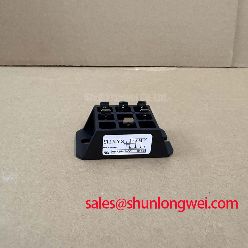
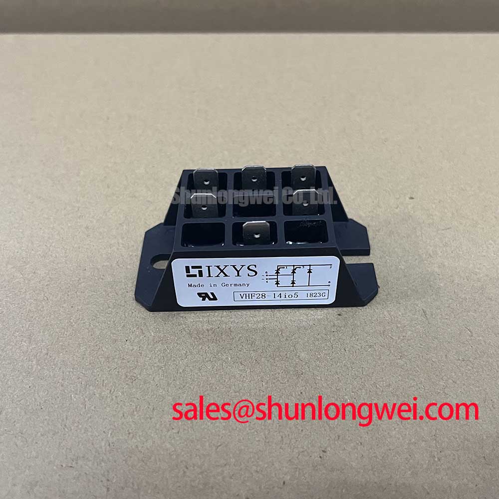



Content last revised on September 22, 2026
VHF28-14IO5 Thermal-Electrical Considerations: Limiting Turn-On Current Rise
Before evaluating a removed bridge module, use the diode test function to compare each accessible forward current path in the same direction and repeat the test with meter leads reversed. The objective is consistency between equivalent paths, not a universal forward-voltage target. Meter type, test current, temperature, and parallel circuit connections can all change the observed reading. A low-resistance path in both directions, an open path where a comparable path conducts, or a reading altered by attached external circuitry should be investigated with the module electrically isolated.
For equipment containing RC snubbers, MOV protection, or series inductive elements, the 1400V specified voltage rating establishes an important device boundary but does not replace a measured transient review. Design Consideration: the suppression network should be assessed as a complete path, including its wiring, connection quality, capacitor condition, and the voltage appearing at the bridge terminals during the switching event. Its purpose is to limit transient stress generated by the surrounding system, while the final component values and peak-voltage margin must be verified under the actual operating conditions by the system engineer.
A series reactor can alter current rise in a rectifier input path, but its selection cannot be inferred from the bridge module’s nominal current rating alone. Source impedance, capacitor-bank state, line conditions, fuse characteristics, and commanded operating sequence all affect the resulting current. Where a fuse coordination document is available for the equipment, compare the installed fuse class and its published I2t behavior with the original design record. The supplied official parameter set for VHF28-14IO5 does not establish a fuse I2t rating or a surge-current limit, so those values must not be substituted from another rectifier module.
Bench Tip: Disconnect stored-energy capacitors and allow the equipment’s approved discharge procedure to complete before moving meter leads between power terminals.
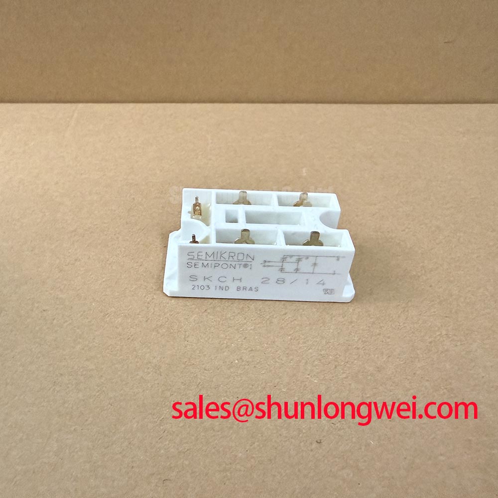
For a dimensional or terminal-layout comparison, SKD 25/14 can be reviewed as a separate reference listing, but matching voltage labels alone does not establish interchangeability. Engineers should verify topology, terminal assignment, current rating, mounting interface, creepage environment, and the original equipment documentation.
VHF28-14IO5 Operational Boundaries: Evaluating AC-to-DC Transfer Characteristics across V Limits
The VHF28-14IO5 is identified as a bridge rectifier module, so a firing-angle analysis must begin by distinguishing the bridge from any external controlled devices used by the host assembly. A diode bridge has no gate terminals to command. In a grid-tied static var compensator or thyristor-switched capacitor installation, external thyristors, contactors, control logic, and capacitor branches can determine the switching sequence; their behavior must not be attributed to this rectifier module.
When technicians assess AC-to-DC transfer behavior across changing control states, record AC source conditions, DC bus voltage, measured load current, and the state of the external switching hardware. This establishes whether the observed result tracks the upstream control sequence, the DC-side load, or a bridge-path abnormality. The 28A specified current rating is a module specification, not a statement of the current waveform, overload profile, capacitor inrush endurance, or reactive-power capability of the complete equipment.
Input current waveform assessment matters because RMS current is tied to conduction heating through I2R loss. The relationship is explained in the industry reference on root mean square current. Design Consideration: use measurements from the actual branch and compare them with the original system limits, rather than treating an average-current reading as a full thermal assessment. Unusual heating can involve connections, heat spreading, source imbalance, capacitor condition, or external control timing as well as the bridge itself.
Similarly, capacitor ESR and ripple-current behavior can influence DC-link ripple and heating elsewhere in the assembly. The reference discussion of capacitor equivalent series resistance is useful when tracing those system-level effects. It does not define an ESR requirement for VHF28-14IO5. The integrator should evaluate capacitor condition using the original equipment criteria and measurements made at the installed operating point.
Preventing Spurious Faults: Separating External Gate-Control Signals from VHF28-14IO5
Do not apply gate pulse, gate rise-time, negative gate-bias, holding-current, or pulse-train requirements to VHF28-14IO5 unless the connected schematic identifies a separate controlled semiconductor. The official information provided for this product identifies a 1400V, 28A bridge rectifier module in a VHF package and provides no gate-drive specification. A gate firing recommendation for this model would therefore be unsupported.
In a system where bridge output appears unstable during thyristor-switched capacitor operation, separate the measurement points. Confirm the rectifier terminal polarity and conduction paths with power removed, then observe the external controller’s command reference, isolation boundary, and controlled-device gate circuit according to the equipment documentation. Common-mode noise, return-path impedance, probe reference placement, and control supply behavior can affect a measured firing waveform. A waveform anomaly may indicate a control-path or layout issue, but it should be verified against a known-good signal path before assigning a component cause.
Engineering Recommendation: keep high-current power connections and sensitive control references organized according to the original physical layout, then verify terminal tightness and cable routing before changing protection components. The VHF28-14IO5 terminal functions and connection arrangement must be confirmed from its applicable manufacturer documentation and the host equipment drawing. No terminal sequence, gate connection, or control-voltage requirement should be assumed from the case description alone.
Where an industrial cabinet also contains monitoring displays or an HMI, system teams can consult The Ultimate Guide to Industrial TFT LCD Technology for display-selection context. That reference is separate from rectifier-module electrical qualification and should not be used to infer any VHF28-14IO5 characteristic.
Assembly Integrity & Layout Architecture: Implementing Mechanical Mounting Torque Sequence for VHF28-14IO5
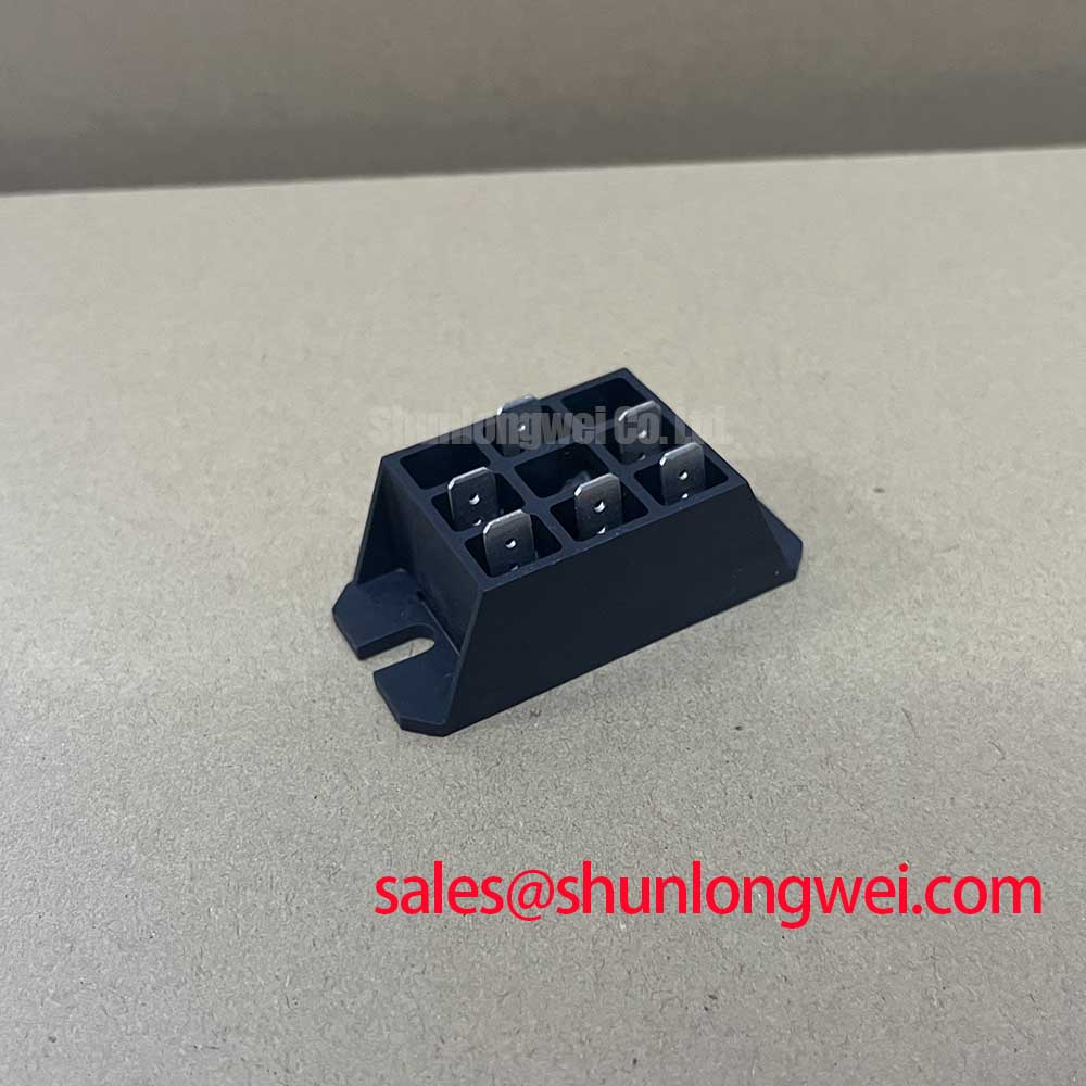
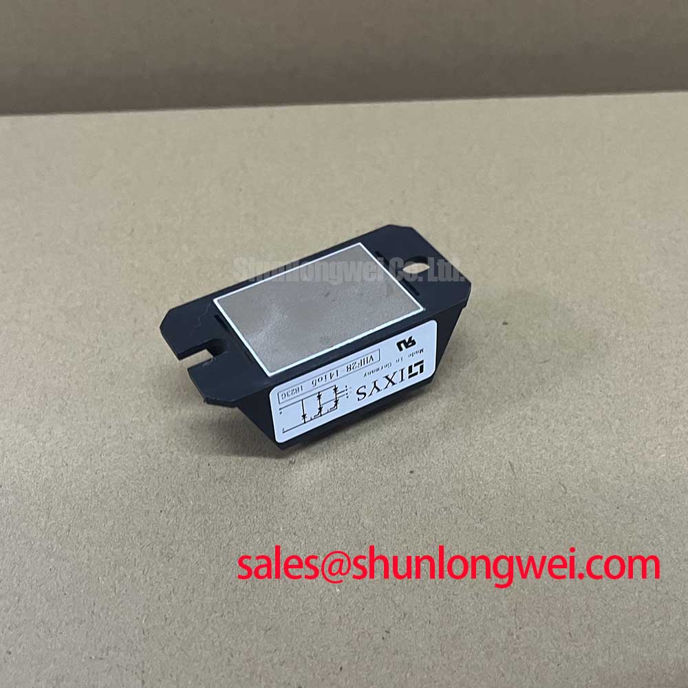
Inspect the VHF package mounting surface and the heatsink for burrs, residue, corrosion, or localized damage before installation. A flat, clean contact surface and controlled fastener sequence help avoid uneven mechanical loading. Apply thermal interface material according to the equipment manufacturer’s approved process, position the module without scraping the interface surface, and tighten mounting hardware progressively in an alternating pattern.
The official information provided here does not state a mounting torque, mounting-hole size, baseplate flatness requirement, thermal resistance value, or maximum junction-temperature limit for VHF28-14IO5. These parameters must be taken from the applicable IXYS documentation and the host equipment service specification. A general mounting torque number must not be presented as an official rating for this model. Design Consideration: use a calibrated tool and follow the documented torque sequence because excessive force or uneven contact pressure can compromise the mechanical interface.
Thermal assessment should combine measured heatsink condition, ambient environment, airflow path, interface quality, and actual electrical loading. The presence of a thermal issue does not identify a single cause. Compare temperature behavior before and after service where a validated reference is available, and confirm that busbar alignment does not impose side-load on the module terminals. Terminal hardware should be tightened only to the approved equipment specification after confirming that conductors are seated without mechanical stress.
For a grid-tied static var compensator or thyristor-switched capacitor assembly, the module should be evaluated as one element of the rectification and protection path. Verify the 1400V and 28A ratings, case interface, terminal mapping, surrounding fuse arrangement, transient-control components, and measured operating stresses before returning the equipment to service.