



Content last revised on September 21, 2026
Transient Dynamics & Electrical Design: High Frequency Switching Loss Dissipation on VS-301MT180C
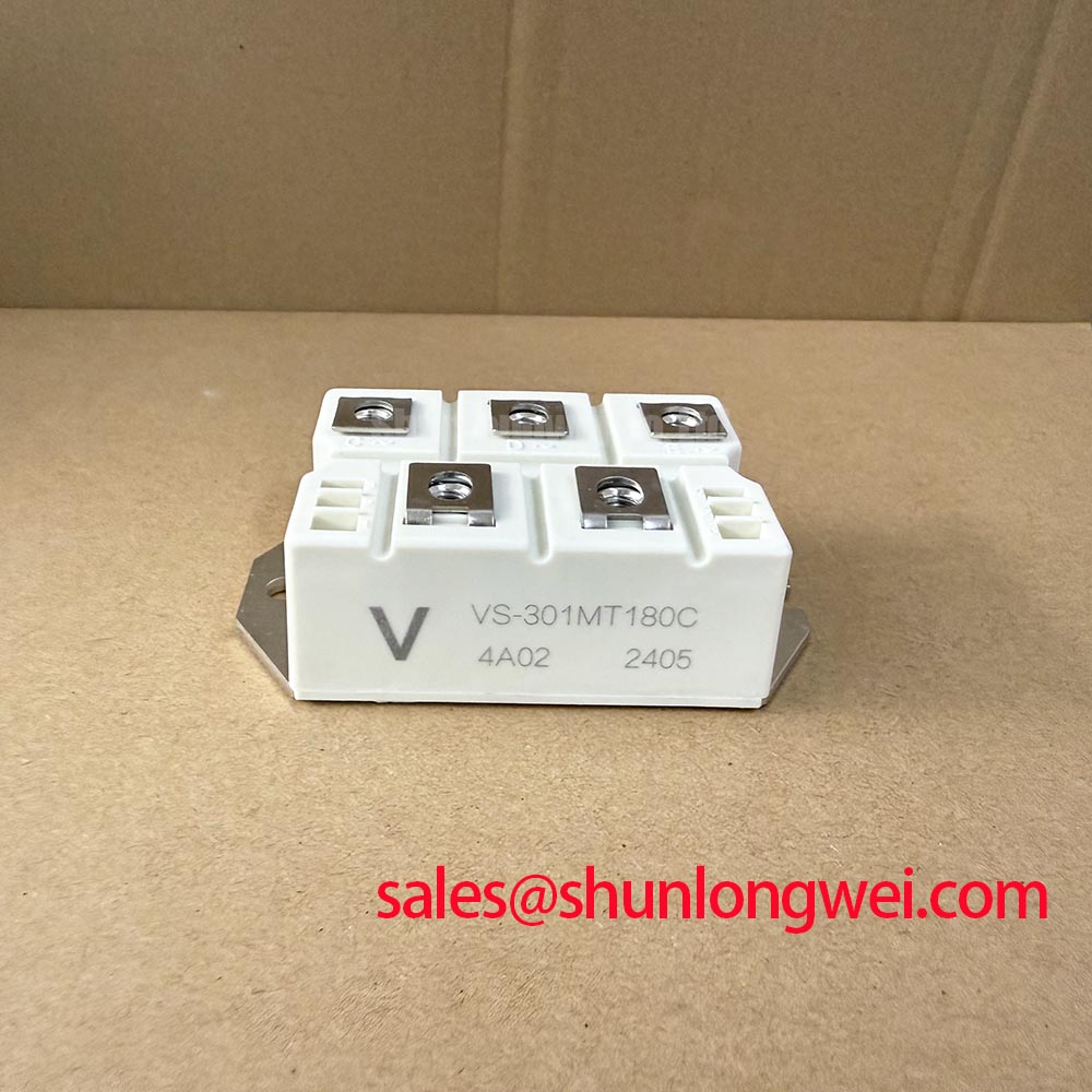
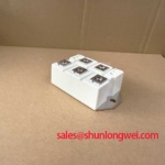
With power isolated and the DC link discharged, first verify the terminal identification and check cold-state conduction paths with a meter before removing the installed VS-301MT180C bridge rectifier module from its chassis-mounted heatsink. This Vishay MTC package unit is rated for 300 A maximum DC output current at case temperature 100 °C, 1800 V maximum repetitive reverse voltage, and 2400 A non-repetitive surge current at 50 Hz. These are Official Datasheet Specifications and should be matched against the failed assembly nameplate, circuit topology, and original protection arrangement before a replacement decision is made.
| Official Specification | Value |
|---|---|
| Manufacturer | Vishay |
| Product Type | Bridge Rectifier Module |
| Package | MTC chassis mount |
| Maximum DC Output Current, IO | 300 A at TC = 100 °C |
| Maximum Repetitive Reverse Voltage, VRRM | 1800 V |
| Maximum Non Repetitive Surge Current, IFSM | 2400 A at 50 Hz |
| Maximum Forward Voltage Drop, VFM | 1.54 V at 300 A |
| Thermal Resistance, Junction to Case, RthJC | 0.038 °C/W |
| RMS Isolation Voltage | 3600 VRMS |
In a rectifier bridge, commutation occurs as current transfers between diode paths. During fault investigation, inspect the AC input conductors, DC output busbar faces, and terminal hardware for heat discoloration, loosened contact surfaces, or evidence of unequal current sharing outside the module. A bridge operating near its rated 300 A output boundary can develop avoidable local heating when a terminal joint adds resistance, even where the semiconductor itself remains within its published voltage rating.
The published maximum forward voltage drop is 1.54 V at 300 A. This is an Official Datasheet Specification that helps technicians understand why high-current rectifier losses must be removed through the mounting base and heatsink path. It is not a fixed prediction of system loss at every load current, temperature, waveform, or commutation condition. Designers should confirm actual operating waveforms and case temperature in the equipment rather than extrapolating a single test-point value across the entire duty cycle.
Reverse-recovery peak current and recovery time are important commutation variables in systems with transformer leakage inductance, capacitor banks, controlled switching, or rapidly changing source impedance. No reverse-recovery value is stated in the supplied official parameters for this model, so a repair engineer should not assign a recovery class or calculate an EMI outcome from assumptions. Design Consideration: minimize high-current commutation loop area to reduce inductive voltage excursions, then verify peak voltage margins against the 1800 V VRRM rating during instrumented switching tests.
For systems containing controlled semiconductor stages, confirm that the bridge is being evaluated as a passive rectifier component rather than as a gate-controlled thyristor or transistor switch. The related TT570N16 may appear elsewhere in power conversion or supply topologies, but its electrical role and connection requirements must be evaluated independently from the VS-301MT180C rectifier bridge.
Carrier transport and recombination affect switching behavior across power semiconductor junctions. For general background on this physical mechanism, technicians may consult Carrier Lifetime and Recombination in Power Semiconductor P-N Junctions. That reference provides device physics context only and does not add unpublished switching specifications to the VS-301MT180C.
VS-301MT180C Thermal Electrical Optimization: Type 2 Coordination: Sub Cycle Dead Short Practical Tuning
A dead-short event must be approached as a protection-coordination review, not as a claim that the module can absorb a particular fuse-clearing event. The official surge-current capability is 2400 A at 50 Hz under the stated non-repetitive condition. It must not be treated as a continuous overload rating, a repetitive fault allowance, or an equivalent fuse I2t capability.
For a practical equipment assessment, record the installed semiconductor fuse part number, its published pre-arcing and total-clearing I2t data, the expected fault-current source, and the location of the fuse relative to the bridge and DC-link capacitors. Compare those documented protection values with the original equipment documentation and the withstand information provided for every device in the fault path. Fuse coordination is system-determined because prospective current, cable impedance, transformer behavior, capacitor discharge, and protective-device timing are all installation-specific.
Do not use the 2400 A surge figure as a substitute for a fuse coordination table. Where the original fuse is unavailable, the safest repair route is to obtain the equipment manufacturer’s protection information or have the complete fault path reviewed by a qualified power-system engineer. This avoids an unsupported assumption that a replacement fuse will protect both the rectifier and surrounding bus structure during a sub-cycle fault.
When checking a failed unit in situ, isolate connected capacitor banks before resistance or diode-mode checks. A low reading can result from stored energy paths, parallel suppression networks, transformer windings, or other parallel devices rather than a conclusive bridge failure. Compare each measured path with the circuit drawing or a known serviceable assembly where available.
Field Alert: Disconnect power, confirm stored energy is discharged, and follow the original hardware torque requirement before loosening or reconnecting high-current terminals.
For maintenance teams evaluating a compatible Vishay-family alternative, VS-ST730C18L0 should be treated as a separate item for documented comparison of voltage class, current capability, package geometry, terminals, isolation requirements, and circuit function. Compatibility cannot be established from a product family relationship alone.
VS-301MT180C Thermal Electrical Optimization: Ensuring Uniform Heatsink Contact Pressure Practical Tuning
The specified junction-to-case thermal resistance is 0.038 °C/W. This Official Datasheet Specification describes the semiconductor-to-case path under specified conditions; it does not include the thermal interface material, heatsink flatness, mounting pressure, airflow, liquid cooling performance, or cabinet temperature. A module can therefore show acceptable bench conduction readings while still overheating after installation if the case-to-heatsink interface is compromised.
Before mounting, inspect the base contact area and heatsink surface for embedded debris, raised burrs, corrosion products, or mechanical damage that can prevent uniform contact. Apply thermal interface material according to the equipment procedure and tighten mounting hardware progressively in an even sequence. Design Consideration: use the mounting torque specified by the module documentation or original equipment assembly instruction, because insufficient force can impair heat transfer while excessive force can distort the package or damage threads.
After commissioning, compare the module case temperature trend under comparable load conditions with a known-good channel when the equipment architecture permits. An abnormal temperature rise may be associated with thermal-interface condition, heatsink performance, unequal electrical loading, restricted cooling, or upstream waveform changes. It should be investigated with measured current and temperature data rather than assigned to one cause without verification.
The module provides 3600 VRMS isolation voltage as an Official Datasheet Specification. This electrical isolation rating should be checked against the installation’s insulation coordination requirements, mounting arrangement, contamination level, and service procedures. It does not independently certify the completed system for EMC, safety, environmental, or insulation-compliance standards.
VS-301MT180C Operational Boundaries: Evaluating Saturable Reactor and Snubber Sizing to Pr Limits
In grid-tied static var compensator and thyristor-switched capacitor equipment, the bridge may be exposed to commutation transients produced by the wider network, capacitor switching activity, transformer leakage effects, and controlled semiconductor stages. The VS-301MT180C has an official repetitive reverse-voltage limit of 1800 V. During service evaluation, measure transient behavior at the module connection points with an appropriately rated differential measurement method and compare observed peaks with the documented device boundary.
Design Consideration: an RC snubber or series saturable reactor can be evaluated when transient energy, voltage rate of change, or current rate of rise produces unacceptable stress in the specific topology. Component values must be determined from the real circuit inductance, capacitance, source impedance, switching sequence, thermal limits, and measured waveforms. The system engineer should validate the final network under normal operation, startup, switching events, and credible fault conditions rather than copying values from an unrelated converter.
Technicians should also inspect whether snubber resistors, capacitors, reactors, and surge suppressors are still connected as intended. A disconnected suppression branch, changed capacitance, degraded resistor, or poor busbar joint may alter the waveform seen by the bridge. These findings may indicate impedance or commutation changes, so verify them with a scope against the documented signal path and equipment design.
For broader context on how power-conversion technologies and system architectures continue to evolve, see Future of Power Electronics. For general information about industrial power semiconductor portfolios, Vishay also provides a reference page for Vishay Siliconix Industrial Power MOSFETs; MOSFET specifications must not be transferred to this bridge rectifier module.