
Content last revised on October 2, 2026
VUO34-16NO1 Operational Boundaries: Evaluating IEC 61000-4-5 Industrial Surge Immunity Limits
| Manufacturer | IXYS |
|---|---|
| Product Category | Bridge Rectifier Module |
| Topology | Three-Phase Bridge Rectifier |
| Rated Voltage | 1600 V |
| Rated Current | 34 A |
| Package | Isolated Module |
| Series | Standard |
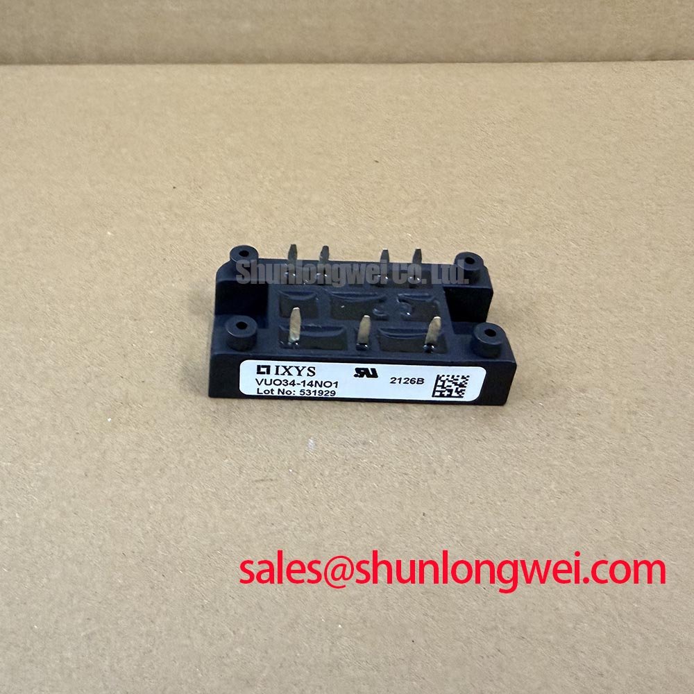
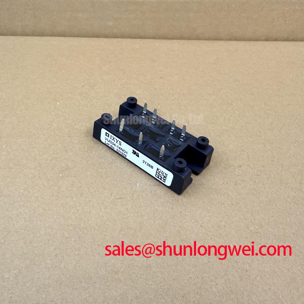
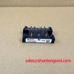
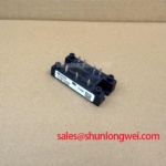
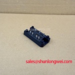
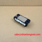
Measure the three AC input paths for unintended continuity to the isolated base and compare the terminal condition with a known-good rectifier before applying an industrial surge test. The VUO34-16NO1 is an IXYS isolated three-phase bridge rectifier module rated at 1600 V and 34 A; these are device ratings, not a declaration that the complete soft starter has passed an IEC 61000-4-5 immunity test.
For a high-voltage three-phase motor solid-state soft starter, the upstream protection network should be evaluated as a complete system. MOV selection, coordinated fusing, and any RC snubber stage must account for the actual line voltage, prospective fault current, surge waveform, and switching arrangement. The supplied product data does not specify a fuse I2t coordination value, surge current rating, or snubber network, so those values must come from the applicable IXYS documentation and the equipment protection study.
Keep surge protection physically associated with the AC input path while minimizing the high-current loop area. A system engineer should verify the voltage appearing at the rectifier terminals during surge testing, then inspect for abnormal leakage, package cracking, terminal discoloration, or a changed cold resistance pattern. The VHF28-16IO5 may be reviewed as a separate rectification-stage reference, but compatibility must be established from the complete circuit topology.
VUO34-16NO1 Circuit Protection & Reliability: Evaluating Post-Surge Reverse Voltage Blocking
After a surge event, isolate every power lead and check the three rectifier paths for consistent diode junction behavior using a controlled test method appropriate to the equipment safety procedure. A difference between phases may indicate semiconductor damage, wiring error, or measurement influence from connected capacitors, so the module should be evaluated outside parallel circuit paths where practical.
The supplied factory parameter set confirms the 1600 V voltage rating and 34 A current rating, but it does not provide an ITSM sinusoidal half-cycle surge value, junction temperature limit, reverse recovery specification, or fuse I2t coordination table. Do not infer post-surge blocking capability from the nominal voltage alone. Obtain the relevant IXYS datasheet revision and confirm the permitted operating conditions before reapplying reverse voltage.
Thermal history also matters during diagnosis. Inspect the mounting interface, bus connections, and surrounding protection components because an overstressed fuse, MOV, or loose terminal can alter the electrical evidence. When comparing alternatives, the VUO82-16NO7 should be assessed by its own voltage, current, package, and surge specifications rather than treated as an automatic substitute.
Assembly Integrity & Layout Architecture: Implementing Harmonic Current Injection and Line Filter for VUO34-16NO1
Capture the three-phase input and rectified output waveforms at the module terminals while the soft starter operates through its intended load range; check phase balance, commutation behavior, and unexpected ringing before changing the line filter. The VUO34-16NO1 provides a three-phase bridge rectifier topology, while input harmonic current, displacement power factor, and reactive power depend on the complete converter, firing control, source impedance, and motor load.
For systems using controlled switching or a downstream thyristor stage, designers should evaluate the interaction between the rectifier, line reactor, EMI filter, and surge suppressors. The firing-angle range and resulting AC-to-DC transfer behavior must be calculated from the actual topology; no firing-angle characteristic is included in the supplied product parameters. Validate the result with voltage and current probes at the equipment terminals rather than assigning a universal power-factor value to the module.
Route high-current conductors symmetrically where the mechanical layout allows, and keep protective components connected with short, low-inductance paths. Gate-drive or control-loop damping belongs to the switching stage and should be tuned from measured waveforms, with peak voltage margins checked against the system DC-link and line conditions. The Power Semiconductor Selection Guide provides a useful framework for comparing ratings, topology, and application constraints.
VUO34-16NO1 Operational Boundaries: Evaluating Mechanical Mounting Torque Sequence and Thermal Limits
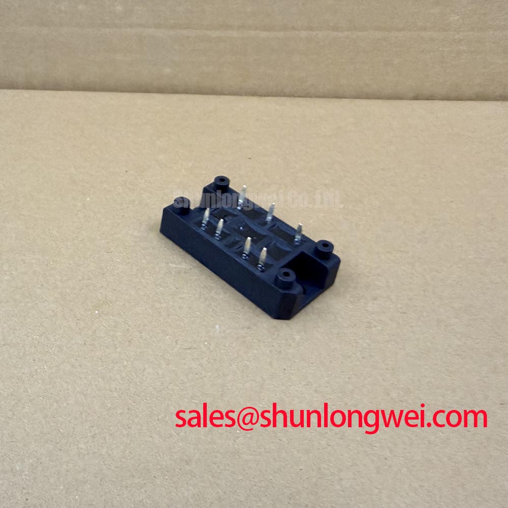
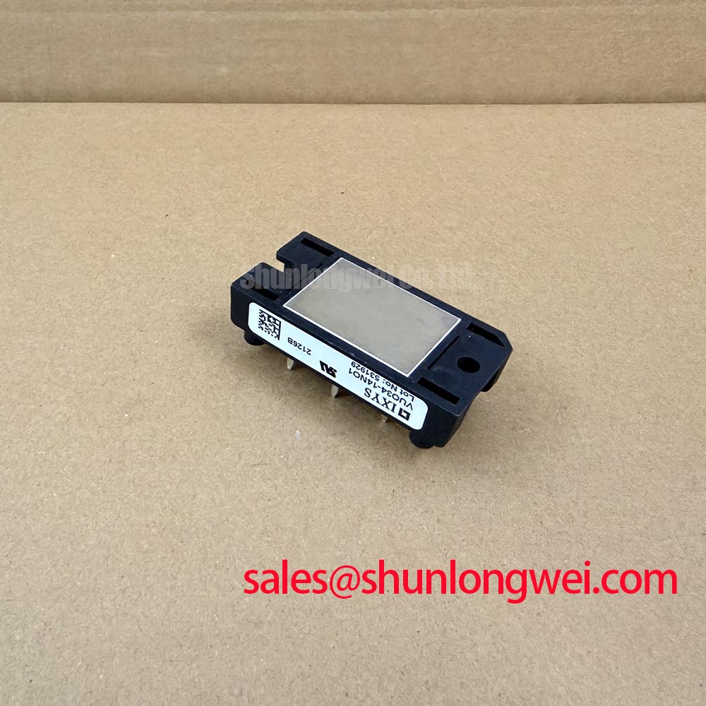
Inspect the baseplate contact pattern and retighten the mounting hardware only according to the applicable IXYS mechanical instructions; uneven contact pressure can produce thermal imbalance even when all electrical terminals appear secure. The package is specified as an isolated module, but the supplied product data does not state baseplate dimensions, thermal resistance, terminal geometry, or an approved mounting torque.
Use a clean, flat heatsink interface and apply the thermal interface material as a thin, uniform layer selected for the assembly’s insulation and temperature requirements. Do not substitute a generic torque value for the manufacturer’s mechanical specification. Fasteners should be tightened in a controlled sequence so the module remains seated without bending or distorting the package.
Thermal verification should use the actual current waveform, switching duty, heatsink arrangement, airflow, ambient temperature, and enclosure conditions. The NEMA enclosure types reference can support enclosure protection planning, but it does not certify this rectifier assembly. Likewise, PPS material information may help explain general high-temperature packaging considerations without establishing the internal material construction of this specific module.
Bench warning: Disconnect the equipment completely and verify the absence of hazardous voltage before removing or inserting any rectifier connection.