


Content last revised on March 28, 2026
1DI300A-120 IGBT Module: Technical Analysis for High-Current Power Conversion
Product Introduction: A Focus on Thermal Efficiency and Ruggedness
Core Specifications and Engineering Value
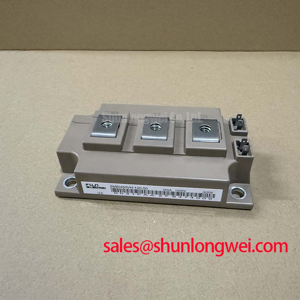
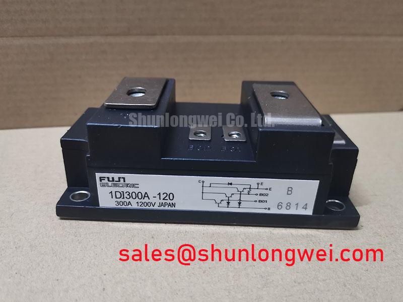
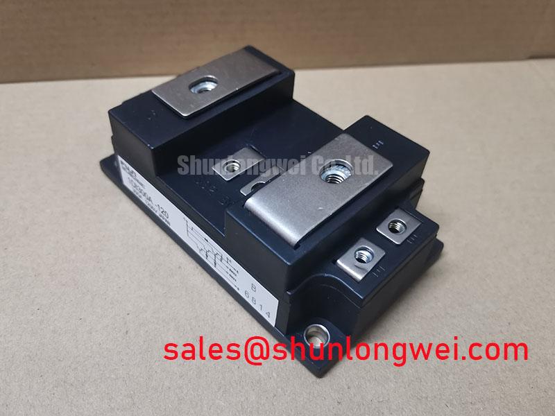
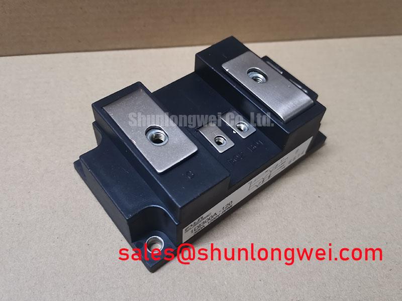
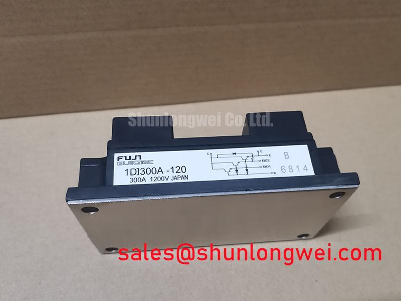
The 1DI300A-120 from Fuji Electric is a 1200V single IGBT module engineered for robust performance in high-power switching applications, delivering a balance of efficiency and durability. With key specifications of 1200V | 300A (DC) | VCE(sat) of 2.7V (typ), this device provides significant engineering benefits, including reduced thermal load and enhanced system ruggedness. It directly addresses the engineering challenge of managing heat in densely packed power cabinets by minimizing conduction losses at the source. For high-current applications where thermal headroom and fault tolerance are critical, the 1DI300A-120 offers a reliable and efficient power switching solution.
Application Scenarios & Value
System-Level Benefits in Industrial Motor Drives and UPS
The 1DI300A-120 is ideally suited for demanding applications where efficient and reliable power control is paramount. Its robust characteristics make it a prime candidate for the inverter stage of industrial systems.
High-Fidelity Engineering Scenario: Inverter Stage of a 150 kW Uninterruptible Power Supply (UPS)
In a data center or critical manufacturing facility, a UPS (Uninterruptible Power Supply) must operate with maximum efficiency to reduce total cost of ownership (TCO) and ensure uptime. The primary challenge for the design engineer is managing the significant heat generated by the power conversion stage. The 1DI300A-120's low collector-emitter saturation voltage (VCE(sat)) of 2.7V at a nominal current of 300A directly translates to lower conduction losses. This reduction in wasted energy, dissipated as heat, allows for the design of a more compact and cost-effective heatsink, contributing to a smaller overall system footprint and improved power density. Furthermore, its excellent short-circuit withstand time provides an essential layer of protection, safeguarding the UPS against downstream faults and enhancing the system's overall reliability.
Other key applications include:
- Variable Frequency Drives (VFD): Efficiently controlling the speed and torque of large AC induction motors in manufacturing, HVAC, and pumping systems.
- Welding Power Supplies: Delivering precise, high-current pulses required for industrial welding processes.
- High-Power Converters: Serving as a robust switching element in various DC-DC and DC-AC power conversion topologies.
While the 1DI300A-120 provides a single switch topology, for designs requiring a complete three-phase bridge in a single module, the 6MBI450U-120 offers a higher level of integration for streamlined assembly.
Key Parameter Overview
Decoding the Specs for Enhanced Thermal Performance and Reliability
The performance of the 1DI300A-120 is defined by a set of critical electrical and thermal parameters. Understanding these specifications is key to optimizing system design for efficiency and long-term reliability.
| Parameter | Symbol | Value | Engineering Implication & Value |
|---|---|---|---|
| Collector-Emitter Voltage | VCES | 1200V | Provides a substantial safety margin for applications running on 480V to 690V AC lines, protecting against voltage transients. |
| Continuous Collector Current (DC) | IC | 300A (Tc=80°C) | Enables high-power throughput, suitable for driving large motors or supporting high-capacity inverters. |
| Collector-Emitter Saturation Voltage | VCE(sat) | 2.7V (typ) / 3.3V (max) @ 300A | Core Efficiency Metric. A low VCE(sat) minimizes power loss during conduction, reducing heat generation and improving overall system efficiency. This is like a low-friction pathway for current, wasting less energy. |
| Gate-Emitter Voltage | VGES | ±20V | Defines the standard gate drive voltage requirements, ensuring compatibility with a wide range of industry-standard gate driver ICs. |
| Short-Circuit Withstand Time | tsc | 10µs | Critical Reliability Feature. This guarantees the module can survive a direct short-circuit for 10 microseconds, allowing time for protection circuits to react and prevent catastrophic failure. |
| Thermal Resistance (Junction-to-Case, IGBT) | Rth(j-c) | 0.085 °C/W (max) | Key to Thermal Management. This value represents the efficiency of heat transfer from the silicon chip to the module's baseplate. A lower number signifies better heat dissipation, enabling higher power density or smaller heatsink designs. |
| Operating Junction Temperature | Tj | +150°C | Specifies the maximum allowable temperature of the IGBT chip, a crucial limit for thermal design and ensuring long-term operational reliability. |
Technical Deep Dive
Analyzing the Impact of VCE(sat) and Thermal Resistance on System Design
The interplay between VCE(sat) and thermal resistance (Rth(j-c)) is fundamental to the successful implementation of the 1DI300A-120. These two parameters dictate not only the electrical efficiency but also the entire thermal management strategy.
VCE(sat) can be thought of as the energy "toll" the current must pay to pass through the IGBT when it is switched on. A lower toll, like the 2.7V typical value of this module, means less energy is converted into waste heat (conduction loss). This is the first step towards an efficient system. However, the heat that is inevitably generated must be evacuated effectively. This is where Rth(j-c) becomes critical. Think of thermal resistance as the width of a highway for heat. A low Rth(j-c) of 0.085 °C/W acts like a wide, multi-lane superhighway, allowing thermal energy to escape the semiconductor junction and travel to the case with minimal obstruction. A high thermal resistance, in contrast, would be like a narrow, congested road, causing heat to back up and elevate the junction temperature dangerously.
By combining low heat generation (low VCE(sat)) with an efficient heat evacuation path (low Rth), the 1DI300A-120 enables designers to either push for higher output power within a given thermal budget or to reduce the size, weight, and cost of the required cooling system, a significant advantage in competitive industrial markets.
Frequently Asked Questions (FAQ)
Engineering Inquiries on Implementation and Performance
What is the primary benefit of the 1DI300A-120's low VCE(sat) in a motor drive application?
The low VCE(sat) directly reduces conduction power losses, which are a major source of heat in the Variable Frequency Drive (VFD). This results in higher drive efficiency, lower operating temperatures, and potentially allows for a smaller, less expensive heatsink, improving the power density and TCO of the final product.
How does the 10µs short-circuit withstand time impact system design?
It provides a crucial safety margin. This rating ensures the module can survive a fault condition long enough for the gate drive's protection circuitry (desaturation detection) to safely shut down the IGBT. This prevents catastrophic failure and improves the overall ruggedness and field reliability of the equipment.
What gate driver considerations are important for the 1DI300A-120?
A driver capable of providing a clean +15V turn-on and a -5V to -15V turn-off voltage is recommended. The negative turn-off voltage is crucial for ensuring immunity to parasitic turn-on caused by high dv/dt, especially in bridge configurations. The driver must also be able to source and sink sufficient peak current to charge and discharge the IGBT's gate capacitance efficiently to minimize switching losses.
Can the 1DI300A-120 be used in parallel to achieve higher current ratings?
Yes, IGBT modules like this can be paralleled. However, successful paralleling requires careful attention to gate drive symmetry, busbar layout to ensure balanced current sharing, and thermal management to keep the modules at similar temperatures. Mismatches can lead to one module carrying a disproportionate amount of current, risking premature failure. For more details, explore best practices for IGBT paralleling.
What does the Rth(j-c) of 0.085 °C/W mean for heatsink selection?
It signifies a highly efficient thermal path from the IGBT chip to the module's baseplate. This low resistance value means that for every watt of power dissipated as heat, the junction temperature will only rise by 0.085°C above the case temperature. This allows engineers to use a smaller or less complex heatsink to maintain the junction temperature below the 150°C maximum, even under high load conditions.
An Engineer's Perspective
Final Design Considerations
When integrating the 1DI300A-120, engineers should prioritize a low-inductance busbar design to minimize voltage overshoots during high-speed switching events. A well-designed gate drive circuit with a clean power supply and short, twisted-pair wiring to the gate and emitter terminals is non-negotiable for leveraging the module's full performance potential. Proper mounting torque and the application of a high-quality thermal interface material are equally critical to fully realize the benefits of its low thermal resistance and ensure reliable operation over the product's entire lifecycle.