
Content last revised on September 10, 2026
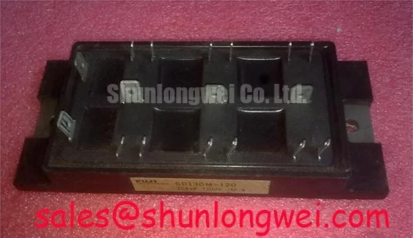
6DI30M-120 Fuji Electric 1200 V 30 A Power Transistor Darlington Module
Before energizing a replacement, isolate the module and record the cold resistance or diode test readings between the marked power terminals, then compare the results with a known good unit from the same equipment. Confirm the terminal lettering from the original Fuji Electric documentation because the available specification data does not define a universal pin order, base arrangement, Kelvin terminal, or package drawing.
| Parameter | Official Specification |
|---|---|
| Manufacturer | Fuji Electric |
| Product category | Power Transistor / Darlington Module |
| Collector Base Voltage, VCBO | 1200 V |
| Collector Emitter Voltage, VCEO | 1200 V |
| Emitter Base Voltage, VEBO | 10 V |
| Continuous Collector Current, IC | 30 A |
| Peak Collector Current, ICP | 60 A |
| Collector Power Dissipation, PC | 230 W |
| Base Current, IB | 3 A |
| Peak Base Current, IBP | 6 A |
| Isolation Voltage, Viso | 2500 V AC for 1 minute |
| Module weight | 400 g |
💡 Bench Tip: Use ESD protection, discharge the surrounding DC bus, and establish a cold state baseline before interpreting any multimeter reading.
6DI30M-120 Thermal Electrical Optimization for Common Mode Bearing Current
Long motor cables can create impedance discontinuities between the switching stage, cable, and motor. In a traction inverter, the resulting reflections may increase terminal overshoot and common mode current. This is a system level design consideration, not a guaranteed behavior or rating of the 6DI30M-120 itself. Designers should inspect the complete switching loop, cable arrangement, motor frame bonding, and return path before selecting a dv/dt filter or common mode choke.
During troubleshooting, compare collector voltage and current waveforms at the module terminals rather than relying only on the controller display. A high frequency ringing pattern can also arise from probe grounding, loose bus connections, unsuitable snubber placement, or impedance mismatch in the motor leads. Verify the measurement setup with a short ground connection and compare it against the original operating waveform where available. Filter selection should be based on measured switching stress, motor insulation requirements, drive efficiency, and thermal behavior.
The listed 1200 V VCEO rating and 30 A continuous collector current rating are important device limits under their specified conditions, but they do not replace a complete transient margin review. The system engineer should verify peak voltage, current duration, conduction loss, and junction temperature under the actual forklift traction duty cycle.
Assembly Integrity and Layout Architecture for the 6DI30M-120
Incoming inspection should begin with the case, terminal condition, mounting interface, and identification markings. The supplied data specifies a module weight of 400 g, but it does not provide package dimensions, baseplate flatness, mounting-hole geometry, or a manufacturer-approved torque value. Use the original mechanical drawing or equipment service documentation to establish those details rather than transferring a generic module installation value.
Where the module uses a metal mounting surface, the thermal interface material should be applied as a uniform, controlled layer without contamination or trapped air. Baseplate convexity, heatsink flatness, screw sequence, and clamping force can affect thermal contact. These are general assembly considerations, not official 6DI30M-120 specifications. Designers should verify contact pressure and thermal resistance through the actual mounting arrangement.
The control wiring should keep the base or drive return path separate from high current collector and emitter conductors. The available product data does not confirm a Kelvin emitter or dedicated auxiliary terminal, so the integrator must verify the terminal drawing before applying a Kelvin layout. Base-drive sourcing and sinking capability, external damping resistance, and loop inductance should be selected from the switching waveform. Adjustments should suppress ringing without creating excessive switching loss or delayed turn off.
⚠️ Field Alert: Do not insert or remove the module, control connector, or driver wiring while the DC bus or auxiliary supply remains energized.
6DI30M-120 Circuit Protection and Dynamic Drive Control
The official data identifies this product as a power transistor or Darlington module and provides collector, emitter, base, and isolation ratings. It does not specify a preferred drive voltage, base resistance, switching frequency, negative bias, active base clamp, short circuit withstand time, or surge energy. Those values must therefore be taken from the original Fuji Electric application documentation or calculated and validated for the complete circuit.
For a forklift traction controller, a driver review should include turn on and turn off timing, base current capability, supply decoupling, and the return path between the driver and module. High dv/dt can couple into the drive circuit through parasitic capacitance and may produce unwanted conduction. A suitable base pull-down or clamp network can be considered when waveform measurements show that the available driver does not hold the control terminal firmly during the opposing switch transition, but the required architecture remains system determined.
Protection validation should include a controlled check of collector emitter voltage, base current, load current, and temperature during acceleration, regenerative braking, and stall related events. Do not infer failure from one resistance reading alone. Compare all terminals with the known good reference and inspect the surrounding driver, snubber, fuse, bus capacitor, and load wiring.
For a neutral replacement evaluation, engineers may also compare the electrical outline and drive requirements of 7MBR15PE120, provided the original equipment documentation confirms mechanical, electrical, and control compatibility.
6DI30M-120 Transient Dynamics and Isolation Verification
The specified isolation value is 2500 V AC for 1 minute. This is the available official isolation specification and should not be reinterpreted as reinforced isolation, a system safety certification, or a common mode transient immunity rating. The product information supplied here does not establish CMTI, clearance, creepage, altitude derating, EMC compliance, or insulation lifetime.
When integrating the module into an isolated traction controller, verify the isolation barrier at the driver and power stage level, including PCB spacing, contamination conditions, connector construction, and the protective earth arrangement. A module cannot independently claim compliance with an overall CISPR or EN 55011 installation requirement. Common mode transient testing should be performed with the actual switching voltage, cable routing, motor connection, and measurement instruments.
For background on switching behavior, parasitic inductance, insulation stress, and power semiconductor failure mechanisms, consult the The Ultimate IGBT Knowledge Base. Manufacturer context for power semiconductor technology is available from Fuji Electric Global Power Semiconductor Technologies. The final acceptance decision should remain tied to the original circuit documentation, measured waveforms, thermal test results, and the official Fuji Electric data applicable to the exact production variant.