

Content last revised on October 13, 2026
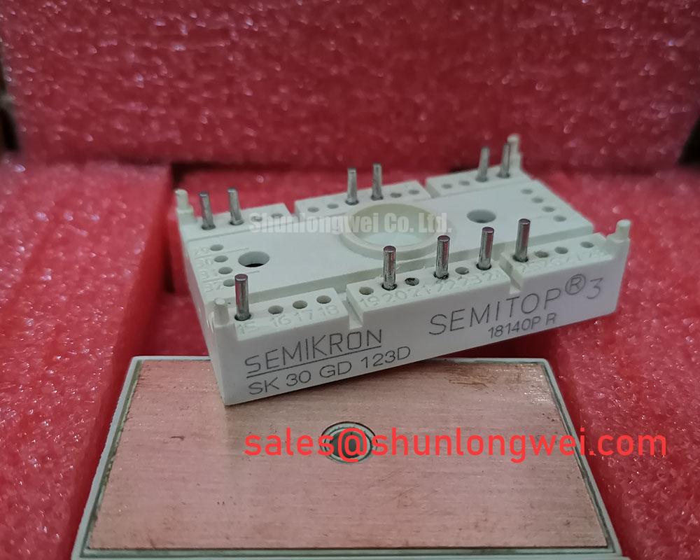
SK30GD123D Thermal-Electrical Optimization: Antiparallel Freewheeling Diode Reverse Recovery Practical Tuning
I capture the commutating current and collector-to-emitter voltage together when investigating turn-on ringing around the SK30GD123D, rather than adjusting the gate resistor from the voltage trace alone. With the power circuit isolated and the DC link discharged, first map the installed module connections against the equipment schematic and manufacturer circuit diagram. This establishes the relevant freewheeling path, probe locations and switching device before an energized test.
Design Consideration: During commutation of an antiparallel freewheeling diode, reverse recovery contributes current to the incoming switch. Peak reverse recovery current, commonly designated I_rrm, and the rate at which that recovery current collapses influence overshoot and ringing. Their measured behavior depends on operating current, junction temperature, switching speed and the surrounding circuit. Treat them as waveform characteristics to evaluate under representative conditions, not as fixed values inferred from the module’s 30 A rating.
For useful measurements, keep the current measurement path and differential voltage probe connections compact, with probe ratings appropriate to the circuit. Compare the switching event at different load and thermal conditions while maintaining consistent probe placement. A ringing frequency that changes substantially when the probe arrangement changes warrants checking the measurement setup before modifying the power stage. Examine the gate waveform alongside the power waveforms to distinguish commutation ringing from unwanted gate excitation.
Turn-on gate resistance is a tuning variable, not a universal cure. Increasing damping can moderate the commutating current slope, but it can also increase switching energy and device temperature. An RC snubber introduces another tradeoff between transient damping and dissipated power. Its component values and pulse ratings should follow measured circuit behavior, with thermal checks over the intended operating cycle. Avoid selecting either solution solely because it improves one oscilloscope screenshot.
Keep the gate drive and its return path closely coupled, and route them away from high-current commutation conductors. Shared return impedance can disturb the effective gate voltage, while collector voltage transitions can couple through gate-to-collector capacitance. Designers should assess driver sink capability, gate-loop damping and any Miller suppression function against measured off-state gate behavior. The required implementation remains a system decision; no particular gate voltage or resistance follows from the supplied headline ratings.
The 1200 V official voltage rating provides a device boundary for evaluating the measured collector-to-emitter waveform. Assess that waveform during switching and abnormal operating transitions, including the influence of DC-link voltage and local overshoot. Use the Semikron-Danfoss Power Electronics & Modules Official Hub for manufacturer technical documentation and application guidance. Module selection, gate-drive tuning and electromagnetic emissions remain separate checks; a semiconductor module does not establish equipment-level EMC compliance.
Assembly Integrity & Layout Architecture: Implementing Braking Resistors and Chopper Transistors for SK30GD123D
Trace the regenerative current path from the motor-side switching stage to the DC-link capacitor and braking branch before assessing braking hardware around the SK30GD123D. Establish from the circuit diagram which device switches the braking resistor and how that device is controlled. Do not assign a braking function to a module terminal from its part number or package name. The braking switch must be identified independently of the inverter’s current rating.
Design Consideration: A braking resistor is selected from the energy entering the DC link, the permitted bus-voltage range and the repetition of deceleration events. Review rotating inertia, operating speed changes and any externally driven load contribution. Resistor pulse-energy capability, average dissipation, enclosure ventilation and temperature monitoring all matter. A resistor that accommodates an isolated stop can still overheat during repeated braking, so the equipment duty cycle should govern evaluation.
The braking transistor requires its own assessment of switching stress, conduction loss, transient thermal behavior and protection response. Check the controller’s braking command against actual DC-link voltage and resistor current during commissioning. If the bus continues rising, investigate command timing, current-path continuity, resistor condition and the energy returned by the load. That observation alone does not identify the module as the failed component.
Reduce the area of the commutation loop formed by the switch, local DC-link decoupling and return conductor. Closely coupled outgoing and return busbar paths can help contain parasitic inductance, provided their insulation and mechanical support suit the equipment. Where a snubber film capacitor is used, its connection should be short enough to act on the local transient rather than through a remote wiring loop. Validate voltage stress and capacitor heating with the completed assembly, including the actual terminal hardware.
Pro Tip: Use balanced, closely coupled busbar paths to limit switching-loop inductance, then validate turn-off voltage margin with a controlled double-pulse test before accepting the layout.
Electrical clearance and creepage around the module must be assessed with the installed busbars, washers, cable lugs and insulating barriers in place. Screw heads and conductor edges can reduce spacing that appeared adequate in the bare mechanical drawing. Select spacing from the applicable equipment insulation requirements, considering working voltage, pollution conditions, insulating materials and installation environment. Do not treat the Semitrans package designation as an insulation-distance specification.
When reviewing an upstream or auxiliary power stage, the SKKR200/0.2-BVR can be considered as a separate component subject to its own circuit function and ratings; its presence does not establish compatibility with the SK30GD123D. Likewise, coordinate semiconductor fuses and electronic fault shutdown against the complete fault path. Fuse I²t is relevant to protective coordination, but it does not by itself establish that an IGBT will survive a short circuit or that the assembly will safely contain a failure.
Field Diagnostics & Commissioning: Preventing Connection Stress in SK30GD123D Topologies
Check terminal seating and busbar alignment before tightening the SK30GD123D assembly: the conductors should meet their mating surfaces without using the fasteners to pull them into position. Select screw length, thread engagement and washers from the specified terminal geometry. A screw reaching the end of its available travel can produce apparent tightening without proper contact pressure, while misaligned conductors can transmit bending loads into the module connection.
Engineering Recommendation: Support heavy cables and busbars independently, allowing the module terminals to make the electrical connection rather than carry the assembly’s mechanical weight. Inspect for witness marks, distorted lugs, damaged threads and changes in conductor alignment after service. These observations support an assessment of connection stress; they do not prove internal leadframe cracking or identify an undocumented internal construction.
Prepare the cooling interface by checking heat-sink cleanliness and flatness, then apply the specified thermal interface material according to the mounting instructions. Excess material, trapped contamination and uneven fastening can impair contact or introduce mechanical stress. Use the manufacturer’s mounting sequence and torque requirements for the actual hardware. Neither a generic screw-size torque nor an assumed grease thickness should replace those requirements.
For an intermittent power connection, combine de-energized continuity checks with controlled operating measurements of voltage drop and local temperature. Compare equivalent current paths under comparable loading, and account for accessibility and measurement uncertainty. A warm terminal may reflect contact resistance, conductor heating or nearby losses. Investigate the connection stack and loading before attributing the observation to an internal module defect.
In replacement assessment, compare the SK30GD123D with candidates such as SK15DGDL126ET through circuit configuration, terminal mapping, electrical limits, switching behavior and mechanical fit. A related manufacturer designation does not establish interchangeability. High-dynamics multi-axis CNC and robotics servo equipment provides one possible evaluation context, subject to the installed drive topology, regenerative duty and protection scheme.
For a broader technology comparison, Wide Bandgap Revolution discusses GaN and SiC design considerations; it is not a replacement qualification document for this IGBT module. After assembly work, commission the existing system through controlled load changes and braking events, recording terminal behavior, gate waveforms and cooling performance. Reinspect supported conductors and fastening interfaces after thermal stabilization, addressing any movement or abnormal contact heating before returning the equipment to its operating duty.