


Content last revised on September 10, 2026
Dynamic Pulse Width and Frequency Sizing for Phosphor Luminance and Power Dissipation Balance
| Model | LJ64ZU35 |
| Manufacturer | Sharp |
| Product Category | Industrial HMI Display Panel |
| Panel Technology | Electroluminescent EL Panel |
| Specification Status | Verify detailed specifications against applicable Sharp documentation |
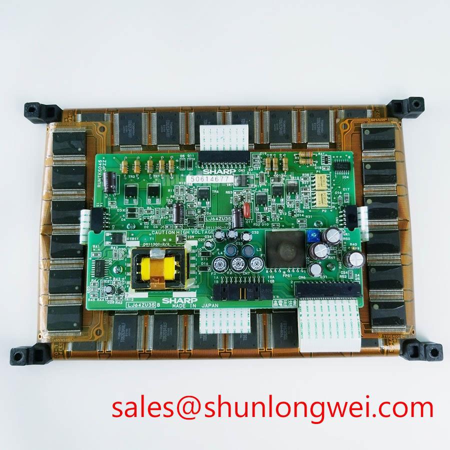
Probe the display driver output at the disconnected panel interface and confirm that the controller is producing a balanced alternating waveform rather than leaving a measurable persistent DC component across the EL load. The LJ64ZU35 is identified as a Sharp electroluminescent panel, so the condition of the high voltage excitation stage matters as much as the panel itself during a dark screen or reduced luminance investigation.
Electroluminescent displays depend on alternating excitation to produce visible emission. A drive waveform with an unintended DC offset can place an uneven electrical burden on the panel dielectric structure and can also distort the apparent brightness pattern. The waveform must therefore be checked under the operating conditions of the original controller, with attention to waveform symmetry, repeatability, ringing, and the difference between an unloaded measurement and a measurement taken with the panel connected.
Some legacy EL driver discussions reference symmetrical alternating high voltage pulses in the 180 V to 240 V peak range with net zero DC bias. This range is a Design Consideration, not an official electrical rating stated for the LJ64ZU35 in the verified product information. The system integrator should verify the required supply voltage, waveform limits, pulse timing, and panel connection arrangement from the original panel documentation and the host equipment service information.
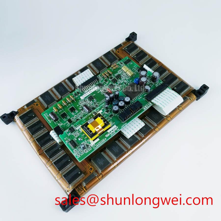
Where a driver includes charge recovery or resonant energy transfer, inspect the associated capacitors, inductive elements, switching devices, and solder joints before condemning the panel. A resonant stage that has drifted away from its intended operating condition may cause uneven light output, audible switching noise, higher driver temperature, or unstable startup. The electrical principle is familiar from an LC circuit: energy can circulate between inductive and capacitive elements, but the practical waveform and peak electrical stress must be validated in the installed equipment.
Measure the waveform with suitable high voltage instrumentation and with safe isolation practices. A standard oscilloscope probe may not be appropriate for the expected signal level or floating reference condition. Compare the affected assembly against a known stable unit when one is available, and inspect whether the driver output changes after enclosure temperature stabilizes. A brightness issue may arise from the driver, connector contact condition, cable strain, grounding arrangement, or the panel itself; waveform observation separates these possibilities more effectively than visual inspection alone.
For control cabinets that use pulse width or frequency adjustment for brightness control, preserve the host controller’s intended timing relationship rather than applying a generic adjustment value. Longer excitation or higher repetition can alter visible output and electrical loading at the same time. The correct operating point is system determined and should be verified through switching tests, thermal observation of the driver assembly, and stable display operation over the equipment’s normal duty cycle.
Luminance Service Assessment Without Liquid Crystal Thermal Assumptions
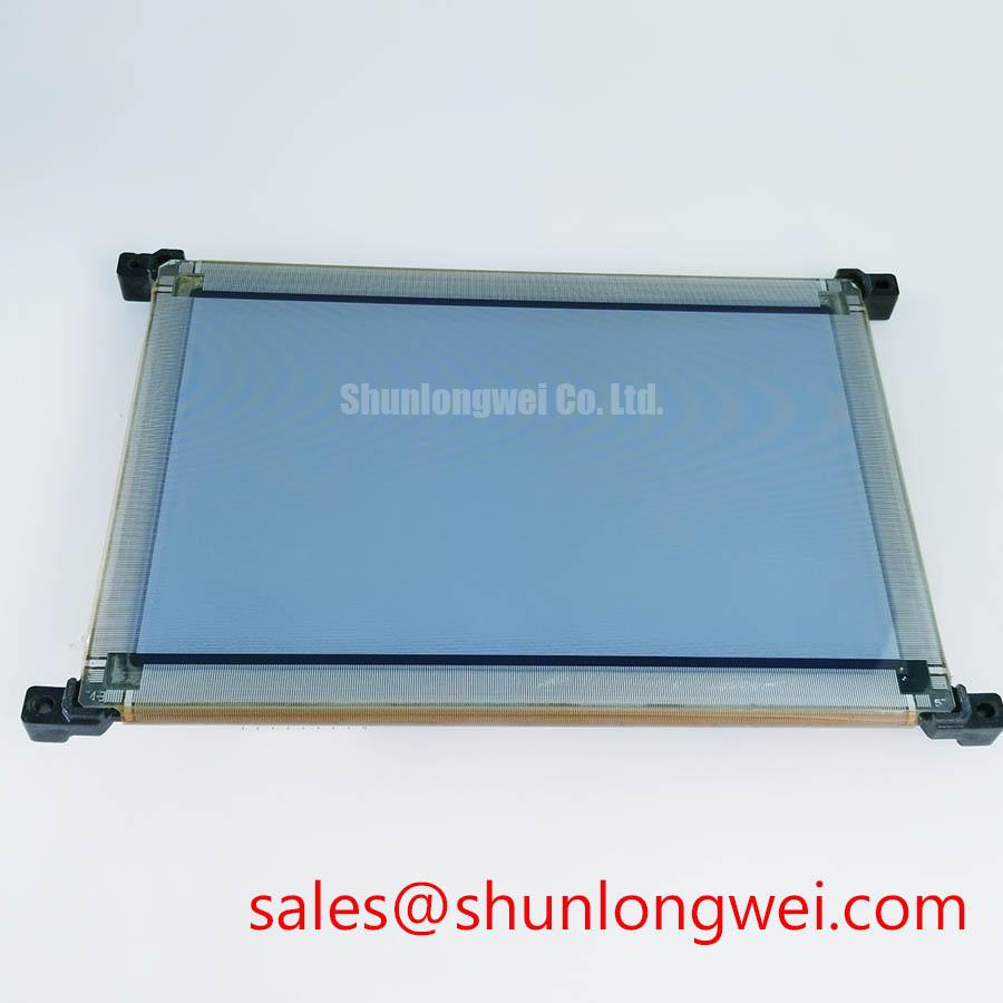
Inspect the active viewing area after the assembly has reached its normal cabinet temperature, then compare uniformity, edge brightness, and intermittent behavior while lightly observing the harness and driver connection for movement sensitivity. The LJ64ZU35 is an EL panel, and maintenance decisions should not rely on troubleshooting assumptions used for liquid crystal displays, including assumptions about liquid crystal fluid response or conventional backlight behavior.
EL technology is often evaluated in industrial HMI restoration work because the panel produces light through its electroluminescent operating principle rather than through a separate LCD backlight arrangement. That distinction changes the service approach. A dim or nonuniform screen warrants examination of the excitation circuit, panel contact path, controller timing, enclosure contamination, and the physical support of the display assembly. It does not justify assigning a service-life figure or a luminance half-life figure to this specific model without a corresponding Sharp factory specification or controlled test source.
Claims such as a luminance half life above 50,000 hours, a 100 G shock rating, sub millisecond response at −40°C, or a 179 degree viewing angle must not be treated as official LJ64ZU35 specifications unless they are confirmed in the applicable Sharp technical documentation. These values are sometimes associated with broader display technology discussions, but they are not present in the verified factory data supplied for this product page.
Cold startup troubleshooting should focus on observed evidence. Inspect for condensation around the display bezel, gasket contact surfaces, power connections, and driver board. A screen that starts inconsistently after a temperature change may indicate a moisture related connection issue, a stressed cable, an aging driver component, or a control signal problem. Record the behavior during controlled warmup rather than treating a single cold event as proof of a panel fault.
Where industrial HMI software leaves fixed icons or static process information visible for extended periods, check whether apparent image retention is temporary, repeatable, or tied to the driver waveform and operating duration. EL panel diagnostics benefit from alternating test images, controlled brightness settings, and comparison against a reference display path. Avoid applying cleaning fluids directly to the active display surface or allowing liquid to migrate behind the front seal.
⚠️ Maintenance Note: Inspect enclosure air paths and perimeter gasket condition during planned maintenance, because trapped contamination or moisture can compromise both display visibility and connector reliability.
Mechanical shock resilience is governed by the complete display assembly, including the host bezel, mounting points, retaining hardware, cable routing, and vibration environment. A panel can appear visually intact while its electrical connection or support geometry has been disturbed. Engineering Recommendation: use mounting hardware that distributes clamping load across the host design’s intended support points, and inspect for uneven bezel pressure where localized stress may create visible nonuniformity or intermittent contact under vibration.
Connector Retention, Flexible Cable Handling, and Controlled Power Sequencing
Examine the connector latch, mating face, strain relief path, and cable bend region under magnification before reconnecting an intermittent LJ64ZU35 assembly. A display can lose illumination or flicker when a connector is partly seated, a locking feature has not fully engaged, or a flexible cable has been repeatedly bent close to its termination.
The verified information identifies the panel type but does not establish a specific interface pinout, connector family, logic supply, or power sequence for this model. Do not infer those requirements from the EL technology category. The system integrator should verify the required supply voltage from the original panel documentation. The host equipment schematic, connector marking, and original cable orientation should remain the controlling references for service work.
When a flexible interconnect is present in the host assembly, support it during removal and insertion rather than pulling it by the conductor section. Check for cracking, permanent creasing, abrasion against sharp metal edges, contamination at contacts, and incomplete latch travel. Cable fatigue can present as a fault that changes when the door is opened, the display bracket is touched, or cabinet vibration changes. That observation narrows the inspection path but does not establish a single cause.
Power sequencing also requires observation at the equipment level. A white, blank, flashing, or residual image condition may be associated with the timing relationship between the controller, EL driver, enable signal, and incoming supply rails. Capture these events at startup and shutdown, then compare them with the operating behavior of a known stable panel and driver combination. Do not install generic timing delays or substitute supply levels without the host design requirements.
For PWM based brightness control, establish whether the host controller applies dimming at the driver enable, a control input, or another dedicated circuit node. A frequency range of 200 Hz to 1 kHz is commonly discussed in general display control practice, but it is not an official LJ64ZU35 requirement. Engineering Recommendation: assess visible flicker, driver stability, and electrical compatibility in the actual equipment rather than assuming that a generic PWM setting is suitable.
When evaluating hardware alternatives, interface compatibility, mechanical fit, controller timing, and optical behavior must all be checked separately. The LM057QC1T08 can be reviewed as a possible alternative during a structured compatibility assessment, but its use must be determined by the original equipment requirements rather than by category similarity alone.
Sealing Pressure, Condensation Control, and Vibration Stress Management
Check the perimeter gasket imprint and bezel contact pattern after removing the panel from its mounting frame, looking for compressed sections, gaps, hardened sealing material, or mounting points that concentrate pressure at one area of the display. Uneven mechanical loading can contribute to visible nonuniformity, unstable mounting, or a path for dust and moisture to enter the front assembly.
The LJ64ZU35 should be installed in accordance with the host equipment’s specified mechanical arrangement. The official factory information available here confirms its Sharp EL panel classification but does not provide mounting torque, bezel force, sealing level, vibration limit, or shock rating. These mechanical values must be taken from the original equipment documentation or the applicable Sharp mechanical drawing.
Design Consideration: release clamping stress evenly by tightening the host mounting points in a balanced sequence and by avoiding a distorted bezel frame. Overcompression can damage gaskets or apply concentrated load to the display perimeter, while insufficient retention can allow vibration movement and cable fretting. The correct fastening condition is determined by the enclosure design, fastener type, panel support scheme, and required environmental seal.
Condensation control begins with the enclosure, not with an assumption about the panel. Inspect cabinet door seals, cable entries, drain paths, heater or ventilation functions, and any evidence of moisture deposition after temperature transitions. Where a display is used in equipment exposed to outdoor brightness, salt laden air, or bridge console conditions, engineers often evaluate enclosure sealing, front window protection, and service access as part of the overall compatibility review. Those conditions are examples for assessment and do not establish a marine environmental rating for the LJ64ZU35 itself.
Vibration diagnosis should include inspection of mounting brackets, connector retention, driver board supports, and cable clearance from moving sheet metal. Intermittent illumination during machinery operation can be checked by observing the driver waveform and supply continuity while the equipment is operating under controlled conditions. In motion control cabinets, the surrounding control architecture may resemble a servo drive environment, where vibration, switching noise, and cabinet heat warrant careful separation of display symptoms from other system activity.
For broader maintenance methods involving enclosure protection, interface verification, and industrial display fault isolation, consult Industrial Display & HMI Solutions as a practical reference alongside the original equipment documentation.