
Content last revised on September 19, 2026
Transient Dynamics & Electrical Design: Mechanical Torque Shock Elimination in Soft Starters with 1000PT18C0
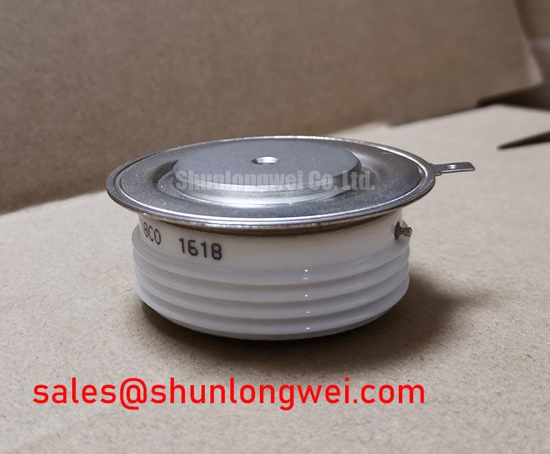
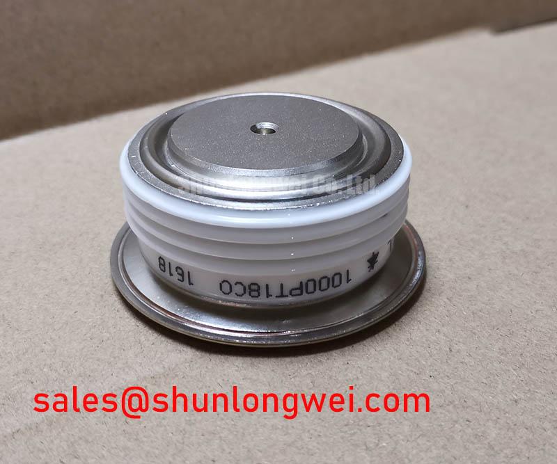
With the assembly isolated from all energy sources, begin by checking the cold-state terminal relationships against the original circuit drawing and by confirming that the installed device marking reads 1000PT18C0. This Vishay power device is specified at 1800.0 V and 1000.0 A, supplied in a Power Block / Bridge Case. Those ratings are Official Datasheet Specifications and establish the electrical identity that must match the existing soft-starter power stage before any integration work begins.
For incoming inspection, use the diode-test function only as a comparative check between equivalent units and known circuit paths. A thyristor or diode module cannot be accepted or rejected from one generic meter reading alone because the measured result can be affected by the surrounding buswork, snubber network, gate circuit, and test-lead polarity. Remove the device from the powered system or isolate its terminals as required by the service procedure before recording measurements.
💡 Bench Tip: Discharge the DC and AC power paths, use ESD-controlled handling around gate connections, and compare cold-state readings with a known-good assembly before reconnecting any control cable.
| Identification Item | Verified Value | Specification Status |
|---|---|---|
| Manufacturer | Vishay | Official product identification |
| Part number | 1000PT18C0 | Official product identification |
| Rated voltage | 1800.0 V | Official Datasheet Specification |
| Rated current | 1000.0 A | Official Datasheet Specification |
| Case style | Power Block / Bridge Case | Official Datasheet Specification |
| Product category | Thyristor/Diode Module | Product classification |
In a high-voltage three-phase motor solid-state soft starter, the first practical check is whether the power-device voltage and current identity remains consistent with the original phase-leg arrangement. The 1800.0 V and 1000.0 A ratings of the 1000PT18C0 are the fixed device-level limits provided for this Vishay unit. They do not, by themselves, establish the allowable motor size, line voltage, overload profile, or starting duty. Those conditions depend on the complete starter architecture, incoming supply waveform, heat sink condition, branch protection, firing control, and motor load.
Phase-angle control can progressively admit portions of each AC half-cycle during acceleration. In a correctly commissioned soft starter, this controlled conduction is used to reduce the abrupt transfer of electromagnetic torque that occurs when a motor is connected directly to the line. Engineering Recommendation: verify the firing sequence with a suitably rated isolated measurement method while comparing phase-current symmetry and line-to-line voltage behavior against the original equipment documentation. A reduced starting-current target should be treated as a system-controlled result rather than as an intrinsic capability of the module.
The practical workshop risk is often a mismatch between the module connection pattern and the existing busbar arrangement. Before applying gate-drive power, inspect terminal faces for contamination, signs of uneven contact pressure, displaced hardware, and evidence of heat at the conductor interface. The original equipment mechanical drawing should govern terminal orientation, conductor stack-up, hardware grade, washer order, and tightening torque. Design Consideration: a broad, clean contact area and even mechanical loading help control contact resistance, which otherwise can create local heating that is not visible in basic static electrical tests.
Fuse coordination must also be checked from the actual protection-device documentation. The fuse clearing characteristics and I²t information need to be evaluated against the fault duty expected at the installation point, while the module’s applicable surge and overload information must come from the matching manufacturer data. Do not substitute a fuse solely because its continuous-current marking resembles the 1000.0 A module rating. The time-current curve, prospective fault current, coordination with upstream protection, and soft-starter bypass arrangement all affect the result.
For a repair evaluation involving a different Vishay part number, the VS-ST730C18L0 can be reviewed as a separate device reference. Its use requires an engineering comparison of voltage class, current capability, terminal geometry, thermal interface, gate requirements, internal circuit configuration, and protection coordination. A shared manufacturer name or similar package family is not evidence of interchangeability.
1000PT18C0 Thermal-Electrical Optimization: High-di/dt Gate Firing: Pulse-Train Timing Practical Tuning
A gate-controlled power stage should be examined at the gate terminals and at the main-current waveform, not inferred from a controller status indicator. For the 1000PT18C0, the official information provided here confirms its 1800.0 V, 1000.0 A identity and Power Block / Bridge Case format; it does not establish a gate trigger current, gate trigger voltage, holding current, latching current, allowable gate-current slew rate, or a preferred pulse-train setting. These values must be taken from the exact manufacturer documentation and from the original starter design.
Engineering Recommendation: inspect the gate wiring for loose crimping, damaged insulation, poor return routing, and unintended coupling from the main power conductors. In high-current phase-control equipment, a weak or distorted firing pulse can produce uneven turn-on behavior between phases. The observable effect may include abnormal current imbalance, irregular acceleration, nuisance protection action, or localized heating, but each symptom requires measurement before assigning a cause.
Pulse-train firing is commonly evaluated where the control system must maintain reliable triggering through changing load current, supply disturbance, or temperature conditions. The relevant question is whether each pulse reaches the intended device gate at the intended phase angle with a clean reference to the correct return path. Use a differential or isolated instrument arrangement appropriate for the circuit’s potential. Compare the captured waveform with the controller specification and with an equivalent healthy phase. Do not connect a standard grounded oscilloscope probe to a floating gate circuit without confirming the measurement safety arrangement.
Thermal performance must be assessed as an assembly condition. Clean the mating surfaces, confirm that the heat sink is flat and free of raised debris, apply the thermal interface material according to the equipment manufacturer’s assembly process, and tighten the mounting hardware in the documented sequence. Design Consideration: uneven fastener loading can compromise thermal transfer and may also stress the case mechanically. The allowable mounting torque for this specific device should be verified in the relevant Vishay mechanical documentation rather than assumed from a general fastener size.
For current verification, a properly selected isolated transducer can be useful when comparing phase currents without breaking the main conductor path. The operating principle of a fluxgate magnetic sensing method provides useful context for low-drift DC and current-transducer measurement concepts, though the selected instrument must be rated and installed for the actual industrial measurement environment. Use recorded waveforms to establish whether a firing issue is repeatable before changing gate-drive components or altering the controller timing.
Preventing Spurious Faults: Sinusoidal 10ms Half-Cycle Surge Current Guidelines for 1000PT18C0
Surge-current assessment begins with the exact 1000PT18C0 manufacturer datasheet, because a sinusoidal 10 ms half-cycle surge value, if applicable, is a device-specific rating that cannot be derived from the continuous 1000.0 A rating. The available official data for this product identification establishes the rated voltage and current only. Service personnel should obtain the exact surge-current and associated I²t information before judging whether a past short-circuit event, stalled motor event, or protection failure remained within the device’s stated limits.
In a motor soft starter, a high transient current can be associated with several system conditions: a motor fault, a locked rotor, a downstream cable defect, an uncontrolled firing event, a bypass-contactor problem, or an upstream supply abnormality. Rather than attributing a fault to a single cause, document the event sequence. Record protective relay indications, phase-current traces where available, fuse condition, controller event history, heat-sink condition, and main-terminal contact condition. This evidence gives the repair team a better basis for deciding whether only the power module requires attention or whether the control and protection paths need investigation.
Before reverse voltage is reapplied after a suspected fault, verify that the system has completed its required de-energization procedure and that the module is not being evaluated while still connected to charged capacitive or auxiliary supplies. Measure the relevant terminals with the approved equipment procedure, then compare cold-state observations among phases where the topology permits. A substantially different reading may indicate a need for further isolation and testing, but it is not a complete diagnosis on its own.
Protection circuits and low-voltage control circuits must remain electrically segregated in accordance with the system design. The concept of Safety Extra Low Voltage and protective extra-low voltage is relevant when evaluating how control-side interfaces are separated from hazardous power circuits. This reference does not certify the 1000PT18C0 or the finished soft starter. Equipment-level safety compliance must be confirmed from the complete system documentation and applicable local requirements.
Where repeated fault indications occur without an obvious damaged power path, check whether all three firing channels reference the correct phase and whether their timing remains consistent under operating voltage. A device that appears acceptable in a static bench check can still require dynamic evaluation in the actual controlled circuit. Conversely, a controller or sensing issue can imitate a main-device failure. Keep these possibilities separate until waveform and continuity evidence supports a repair decision.
1000PT18C0 Operational Boundaries: Evaluating Dynamic Voltage Sharing and RC Damping Limits
RC damping and series-reactor decisions belong to the complete soft-starter design, not to the 1000PT18C0 rating label. The module’s Official Datasheet Specifications of 1800.0 V and 1000.0 A provide essential boundaries, while the actual switching transient depends on cable length, line impedance, busbar layout, contactor behavior, motor characteristics, phase-control angle, snubber condition, and the state of the bypass circuit. Engineering Recommendation: minimize parasitic loop inductance where practical to reduce inductive overshoot, then verify peak voltage margins with isolated switching tests against the measured system voltage.
An RC network should not be copied from another starter merely because it uses a similar current-class module. The required capacitance, resistance, pulse capability, insulation arrangement, and physical placement are determined by the measured transient response and by the original design documentation. A failed or disconnected snubber may contribute to abnormal voltage stress, ringing, or erroneous firing behavior, yet those symptoms can also originate in wiring layout or a control-reference problem. Inspect the network for open connections, cracked terminals, heat exposure, and changed component values using an appropriate isolated test method.
Series-connected power devices require controlled dynamic and static voltage sharing. The associated resistor-capacitor networks, balancing components, and firing timing must be reviewed as a coordinated group. Design Consideration: each parallel or series path should be assessed for equivalent interconnect resistance, connection length, trigger timing, and thermal path before energization. The system engineer should validate current and voltage sharing with measurements under representative conditions rather than relying on physical similarity between installed modules.
Long motor cables and switching interfaces can produce reflected-wave behavior, with voltage peaks that may exceed the local waveform expected from source measurements alone. Where a starter drives a motor through substantial cable length, inspect the original filter, surge-suppression, and cable-termination provisions before assuming the thyristor module is the source of the event. The relevant evaluation is the voltage at the device and at the motor connection under controlled test conditions, using instrumentation rated for the installation.
For repair teams examining firing integrity, transient suppression, and controlled turn-off conditions around high-energy power semiconductors, the practical reference material at Precision Gate Drive Design can support a structured measurement plan. Any gate-drive adjustment, damping change, or protection-threshold change should be validated by the system designer against the original control scheme, measured waveforms, and the applicable manufacturer documentation for the 1000PT18C0.