Content last revised on October 1, 2026
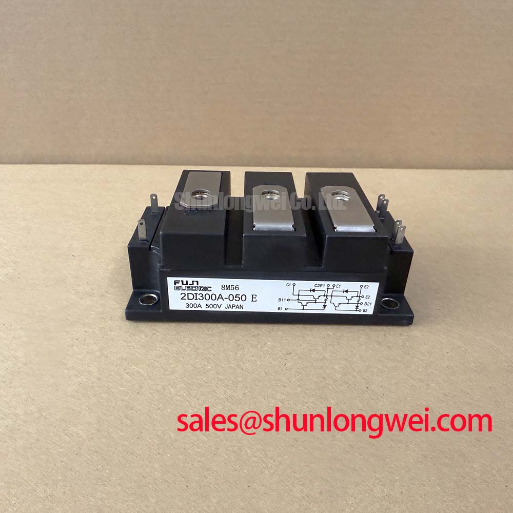
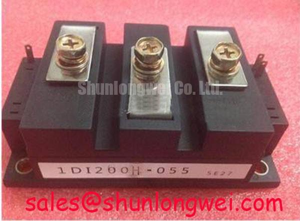
Assembly Integrity and Layout Architecture for 1DI300M-050
| Manufacturer | Fuji Electric |
|---|---|
| Model | 1DI300M-050 |
| Product category | Power Transistor Module |
| Rated voltage | Confirm from the manufacturer’s datasheet |
| Rated current | 300.0 A |
Measure the main terminal path and the drive return with the module isolated, then compare each cold-state reading with an electrically known-good assembly before applying switching power. A substantial difference between parallel current paths may indicate a loose joint, contamination, damaged semiconductor path, or an unsuitable measurement reference.
For a high-current inverter leg, the power emitter return and the base-drive emitter return should be routed as separate circuits wherever the module and driver interface support that arrangement. This is an engineering recommendation for reducing mutual coupling between load current and the drive reference voltage. The main collector and emitter conductors should remain short and mechanically secure, while the drive loop should follow a compact route with its return conductor kept close to the outgoing path.
When evaluating 1DI300M-050 in a commercial string inverter or micro-grid energy-storage converter, inspect busbar overlap, terminal flatness, insulation spacing, and cable restraint together. Layout clearance must be established from the actual DC-link voltage, switching transient measurements, pollution environment, and applicable equipment insulation requirements. Do not infer a module-specific clearance value from its voltage rating alone.
Use an oscilloscope with an appropriate differential probe to compare base-to-emitter behavior at the module terminals rather than at the driver board only. Ringing or a moving reference during turn-on and turn-off can indicate excessive loop inductance, common-mode coupling, or an incorrectly shared emitter return. Fuji Electric’s IGBT module information provides general manufacturer-level context for switching-device interfaces, but it is not a specification for this power transistor module.
Benchtop Waveform Tuning for Battery Cycling Applications
Capture collector-emitter voltage, phase current, base-emitter voltage, and DC-link voltage during both battery charging and discharging tests, then compare the rising and falling transitions under matched load conditions. A four-quadrant battery converter can reverse active power flow, so a waveform that appears acceptable in one direction may expose overshoot or ringing in the opposite direction.
Minimize the commutation loop formed by the module terminals, DC-link capacitor, and switching return path to reduce parasitic inductive voltage. A busbar inductance target must be treated as a system design target, not as an official rating of 1DI300M-050. The final value should be verified with the assembled busbar and switching waveform, especially when high battery current produces rapid thermal and electrical cycling.
Place the local film snubber capacitor at the switching loop that generates the measured transient, with connections kept short and symmetrical. Its voltage rating, pulse-current capability, capacitance, and damping behavior must be selected from measured overshoot and the converter topology. Designers should validate peak voltage against the module’s specified voltage rating and the complete operating temperature range.
During repeated peak-shaving tests, log case temperature, switching waveform changes, drive supply stability, and thermal interface condition together. This helps distinguish electrical overshoot from mounting or cooling variation without assigning a single cause to a complex cycling fault. The thermal management reference can support evaluation of heat-flow and interface decisions at system level.
Overcurrent Detection and Controlled Turn-Off Evaluation
Use a controlled short-circuit or fault-injection bench only with protection equipment rated for the available DC-link energy, and observe the fault-detection signal, drive command, collector-emitter voltage, and turn-off sequence on the same time base. The product information here lists a 300.0 A current rating, but it does not establish a module-specific short-circuit withstand time or fault-detection threshold.
Fault detection and controlled turn-off are driver and system implementation topics. If the protection circuit detects abnormal collector-emitter voltage or current, its response must be coordinated with the transistor’s drive requirements and the converter’s stored energy. The selected delay, filtering, clamp action, and fault latch must be validated against the actual driver, wiring parasitics, DC-link voltage, and fault-test results.
Check the voltage-sense path, sense lead placement, driver reference, and fault-reset behavior during bench troubleshooting. An apparently late response may involve probe delay, sense-loop inductance, driver filtering, or a drive-reference disturbance. Compare the measured response against the driver manufacturer’s timing requirements and the equipment protection study rather than assigning a fixed microsecond value to the power module.
Transient Dynamics, Current Sharing, and Parameter Mismatch
Measure each parallel switching branch independently during turn-on and turn-off, recording base-emitter voltage, collector-emitter voltage, current balance, and terminal temperature. Unequal dynamic current can result from drive-loop mismatch, busbar geometry, driver output variation, or thermal differences even when static resistance measurements appear similar.
Differences in on-state voltage and transistor gain can affect static current sharing between parallel paths, while balanced static measurements do not guarantee balanced dynamic switching. Symmetrical drive wiring, equivalent power-path geometry, and closely matched driver conditions should therefore be treated as design considerations. The system engineer must verify current sharing with current probes under the intended switching frequency, load profile, and temperature range.
For a commercial string inverter or micro-grid storage converter, derating should be established from measured junction or case temperature, switching losses, cooling performance, DC-link conditions, and the equipment’s required transient margin. The 300.0 A rating is a product parameter, not a universal continuous-current guarantee for every enclosure or duty cycle.
When cross-evaluating a related Fuji Electric device, engineers may review 6DI50AH-050 as a separate product record. Any substitution requires confirmation of electrical ratings, terminal arrangement, drive requirements, mechanical fit, thermal path, and protection compatibility. Field Alert: isolate and discharge the DC link before touching terminals or changing drive connections.