
Content last revised on September 28, 2026
243NQ045 Identification and Incoming Inspection
Check the polarity and terminal markings on the 243NQ045 before placing a meter across its power terminals. A diode test can establish which direction conducts at the meter’s test current; it cannot establish the device’s working voltage, surge capability, or fitness for a high-voltage cabinet. For incoming inspection, record the marked part number, case style, terminal arrangement, and cold readings alongside those from a documented reference unit.
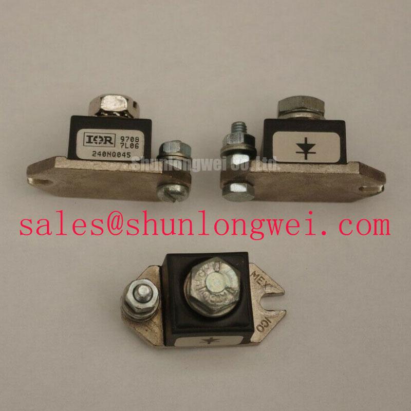
The supplied product parameters identify this Vishay device as a 240 A, 45 V discrete power diode in a Stud Mount / HALF-PAK case. The current rating applies under the manufacturer’s specified conditions. Confirm these figures against the manufacturer documentation for the exact marked part before they are used as equipment limits. In particular, a repair assessment should not infer voltage capability from the part number or from a handheld meter reading.
243NQ045 Circuit Protection & Reliability: Ensuring Uniform Heatsink Contact Pressure
Start the mounting inspection with the mating surfaces. Look for burrs, debris, old compound, and uneven contact marks; then check that the device can seat without force or case distortion. A thin, continuous thermal-interface layer can help fill surface irregularities, but excess compound should not be used to compensate for a warped heatsink. These are Design Considerations, not substitute limits for the device’s published junction-to-case thermal resistance or mounting instructions.
Do not assign a tightening torque from the case description alone. Confirm the exact mounting hardware, terminal connections, torque, and thermal-resistance test conditions in the applicable Vishay drawing before assembly. The same discipline applies to protection: compare the diode’s published surge and thermal limits with the prospective fault current and the selected semiconductor fuse’s clearing characteristics. A fuse marked for high current is not, by that fact alone, coordinated with a diode under a dead short.
💡 Bench Tip: Discharge and isolate the assembly before a cold diode-mode comparison, and keep both meter lead positions in the inspection record. A reading that differs from the reference unit warrants further investigation; it does not, on its own, identify a particular failure mechanism. Where the diode sits in a grid-tied static var compensator or a thyristor-switched capacitor cabinet, also inspect the surrounding insulation barriers and terminal spacing against the equipment documentation rather than assuming that the component’s voltage figure establishes cabinet-level clearance.
243NQ045 Operational Boundaries: Evaluating RC Snubber Network Optimization to Prevent Limits
Trace the installed circuit before changing an RC snubber. A diode can experience reverse-voltage transients during commutation, while switching elsewhere in the assembly can drive additional ringing through shared wiring. The practical task is to capture voltage at the device terminals under representative operation, identify the transient path, and check the measured peak against the verified device limit. Snubber resistance and capacitance are system-selected values; neither can be prescribed from the 243NQ045 current rating alone.
A metal-oxide varistor and an RC network serve different roles and should be evaluated together if both appear on the schematic. The varistor’s operating and surge behavior must suit the equipment voltage and expected events; the RC branch must be checked for its own dissipation and effect on commutation. A series reactor, if present, changes current rise and stored energy, so a change to that part calls for renewed waveform and protection checks. These are Design Considerations for the assembled circuit, not claimed built-in features of this diode.
For a prospective short-circuit assessment, obtain the diode’s manufacturer surge data and the fuse maker’s pre-arcing and total-clearing data at the relevant fault conditions. Compare them with the equipment’s available fault current and wiring layout. Until those documents and conditions are established, an I²t coordination figure or a claim of containment would be unsupported. The discussion of modular power-stage measurement in The Race for Efficiency can provide broader context for reviewing measured stress, but it does not set a limit for this part.
Transient Dynamics & Electrical Design: Distinguishing Diode Operation from Gate Trigger Dynamics
243NQ045 is a diode, not a gate-triggered thyristor. It therefore has no gate pulse rise-time or back-porch holding-current requirement to tune. Applying thyristor firing instructions to its terminals would be a category error. If the equipment includes a separate thyristor, obtain that device’s identification and gate specifications before assessing its trigger board, pulse train, or isolation components.
At the bench, separate diode observations from controller observations. Check the diode’s marked polarity and cold conduction in both meter orientations, then inspect the power connections for signs of poor contact. If a controller fault coincides with commutation, capture the relevant signals using measurement equipment and isolation practices suitable for the cabinet. Common-mode transients at an optocoupler or digital isolator are a Design Consideration for the controller; the required immunity follows from that controller’s measured environment and component documentation, not from the diode designation.
In a repair comparison, 6RI75G-160B should be treated as a separate part to assess, not a presumed replacement: its device type, circuit function, terminals, mounting, and electrical limits must each match the intended position. Likewise, VS-ST730C18L0 may be relevant when reviewing another rectification or controlled-switching position on a system schematic, but its role cannot be inferred from this diode’s rating.
Benchtop Waveform Tuning: AC-to-DC Transfer Characteristics with 243NQ045
Identify which component controls conduction before interpreting an AC-to-DC waveform. A diode conducts according to its applied polarity and circuit conditions; it does not accept a selectable firing angle. If the assembly varies output through firing-angle control, that control belongs to other devices in the topology. Consequently, a calculated output-versus-angle curve cannot be assigned to 243NQ045 without the complete circuit and operating conditions.
For a measured transfer check, log the AC input, DC output, diode-terminal waveform, load condition, and control state together. Compare operating points only after confirming that the probes, references, and schematic identify the same nodes. Changes in power factor or reactive demand in a static var compensator are properties of the assembled system and its control strategy, not standalone specifications of this diode. A monitoring display can help present those measurements; Truly Semiconductors’ industrial display information concerns that separate interface function and does not establish power-semiconductor ratings.
Before returning the cabinet to service, reconcile the part marking with the exact manufacturer documentation, then verify terminal polarity, mounting instructions, insulation spacing, fuse coordination, and captured voltage and current stress under the equipment’s approved test procedure. If the documented blocking-voltage rating does not agree with the supplied 45 V listing value, resolve that discrepancy before treating the device as suitable for the position.