





Content last revised on September 19, 2026
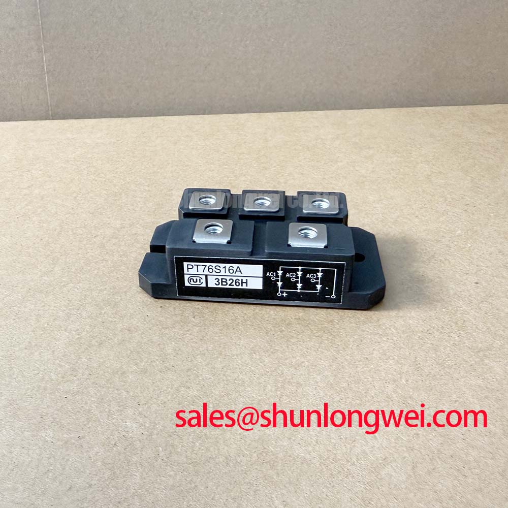
PT76S16A Circuit Protection & Reliability: Fuse Coordination and I2t Protection
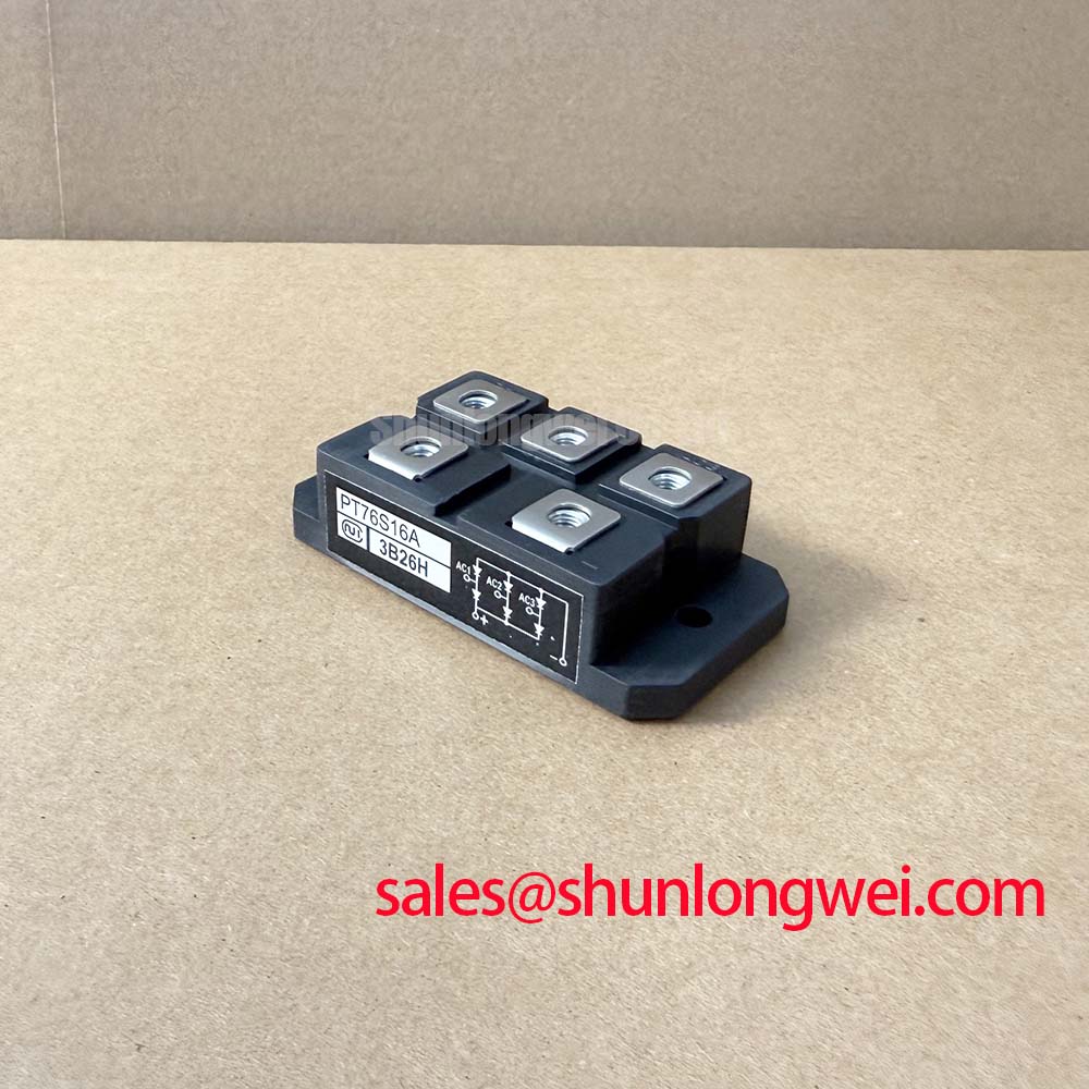
For a high-current green hydrogen electrolyzer DC power rectifier, the protection review should start with the semiconductor fuse and the rectifier fault path. The 1600.0 V voltage class and 76.0 A current class are official device ratings, but they do not by themselves define the acceptable fuse clearing performance for a particular bus, transformer, or commutation network. The system engineer should obtain the fuse manufacturer’s published I2t clearing value and compare it with the PT76S16A withstand information from the relevant device documentation.
This comparison should account for the complete fault loop, including transformer impedance, DC-link conductors, busbar geometry, fuse placement, and the available prospective short-circuit current. A fuse coordination table is required before claiming protection for a dead-short event. Where that table is unavailable, the appropriate engineering position is to hold the circuit in a controlled test state and verify clearing behavior through the approved protection study rather than infer a safe value from the module current rating.
Terminal connections deserve the same attention as the fuse selection. Clean contact surfaces, correctly sized conductors, supported cable weight, and a mechanically stable bus connection help prevent localized heating and unwanted inductive voltage during fault interruption. The mounting hardware and tightening method should follow the original equipment documentation or the NIEC mechanical specification. A general mounting torque value must not be presented as an official PT76S16A parameter without a source.
During replacement evaluation, compare the original circuit topology and terminal identification with the proposed device. The neutral reference for a potential alternative such as PGH50N16 should be established from its own documentation; similar voltage or current markings do not prove mechanical, electrical, or gate-drive interchangeability.
Transient Dynamics & Electrical Design: Sinusoidal 10 ms Half-Cycle Surge Current on PT76S16A
Short-duration surge evaluation should use the exact sinusoidal half-cycle surge-current specification for the PT76S16A, including its stated test conditions and junction-temperature assumptions. The available product data confirms the continuous class as 76.0 A and the voltage class as 1600.0 V, but it does not provide a verified ITSM value in the supplied parameter set. That missing value must be retrieved before a 10 ms surge calculation is used for design release.
In a rectifier feeding an electrolyzer DC stage, the surge event may occur during energization, transformer flux imbalance, capacitor charging, or a transient control sequence. Engineers should record the current waveform, starting junction condition, line phase relationship, and reverse-voltage reapplication point. The measured result should then be checked against the manufacturer’s surge-current curve and the fuse coordination study. A waveform that remains below the nominal current rating for most of a cycle can still produce unacceptable thermal or commutation stress if the peak and recovery conditions are not evaluated together.
Keep the high-current path compact and symmetrical where the topology allows it. This is a Design Consideration for reducing stray inductive voltage during current transfer, not a guaranteed characteristic of the module. The final acceptance decision should come from oscilloscope measurements of current and voltage at the power terminals under the actual bus and transformer conditions.
Safety interlock note: isolate and discharge the DC link before removing terminals or changing the module, then verify the absence of hazardous voltage with an approved meter.
Benchtop Waveform Tuning: Mitigating Stress via Reverse-Recovery Charge Temperature Coefficient on PT76S16A
Reverse-recovery evaluation requires the PT76S16A datasheet curves for reverse-recovery charge, recovery time, peak recovery current, and temperature dependence. Those values are not included in the confirmed product data supplied here, so they should not be substituted with generic thyristor or diode figures. A double-pulse or controlled commutation test can reveal the actual interaction between the module, the opposing switch, the DC-link capacitor, and the physical bus structure.
At the bench, probe placement is important. Voltage should be measured with a suitable high-voltage differential probe, while current measurement should capture the commutation path without adding an excessive loop. Compare the observed recovery peak and ringing with the known-good equipment waveform. An unexpected waveform may indicate layout parasitics, an unsuitable gate timing relationship, probe influence, device mismatch, or a control-loop issue; it should not be assigned to one cause without checking the complete signal path.
Gate-drive behavior also needs verification where the circuit uses controlled thyristor triggering. Confirm the actual gate pulse amplitude, pulse duration, trigger timing, return path, and isolation method against the original design documentation. Designers should minimize gate-loop parasitic inductance and provide appropriate damping when oscillation is observed, while selecting the final network through measured gate and anode-cathode waveforms. The transfer function and loop-gain reference can help engineers separate control-loop behavior from power-stage commutation effects.
Current-sensor behavior should also be checked during the transient. A sensor output that clips, delays, or rings can cause the controller to respond to an inaccurate current value. The operating principles described in the GMR sensor reference provide useful background for interpreting magnetic current-measurement behavior, but the selected sensor and its bandwidth remain system-specific.
Preventing Spurious Faults: Junction-to-Heatsink Heat Dissipation Guidelines for PT76S16A
The PT76S16A uses an isolated power module package, so thermal verification should begin with the approved case interface, heatsink construction, electrical isolation method, and the manufacturer’s published thermal-resistance data. The supplied factory parameters confirm the device voltage and current ratings, but do not provide a verified Rth(j-c) value, maximum junction temperature, baseplate dimensions, or paste specification. These details must be confirmed before calculating a heatsink requirement.
Inspect the heatsink surface for contamination, burrs, distortion, and uneven contact. Apply the interface material according to the original assembly procedure, using enough coverage to eliminate significant air gaps without allowing material to contaminate electrical insulation surfaces. Fasteners should be tightened in the specified sequence and to the documented value for the actual hardware. Designers should verify contact pressure across the module footprint, because excessive or uneven loading can distort the package while insufficient loading can increase thermal impedance.
Thermal testing should use temperatures measured at documented reference points and should include the real rectifier duty cycle, airflow condition, enclosure arrangement, and adjacent heat sources. A rising case temperature can result from electrical overload, poor interface contact, blocked airflow, inaccurate current measurement, or an incorrect loss model. Check these factors together before changing the heatsink or reducing the operating load.
For extreme-environment evaluation, including altitude or radiation exposure, the available product information does not establish FIT, single-event burnout, cosmic-ray withstand, or operating-life figures. Such assessments require a qualified reliability source and the relevant system-level qualification method. The practical next step is to verify voltage and thermal margins through controlled switching tests and consult the Wide Bandgap Revolution reference when comparing broader power-semiconductor design considerations.