


Content last revised on September 28, 2026
CVM50BB160 Thermal Electrical Optimization: Fuse Total Clearing I2t versus Device Melt Practical Tuning
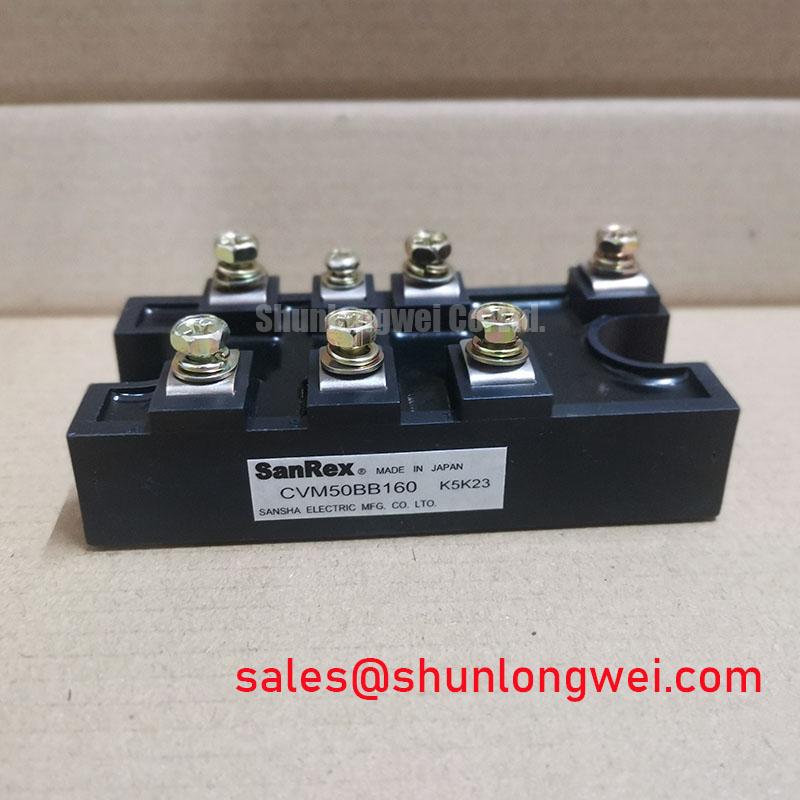
Before energizing a replacement, isolate the rectifier cabinet, inspect the power terminals and housing, and verify the nameplate boundary of 1600.0 V and 50.0 A against the original circuit documentation. The CVM50BB160 is a SanRex (Sansha Electric) Thyristor / Diode Module supplied in a SanRex Power Module package. These are official product parameters; they do not by themselves define the permissible operating current under every cooling, switching, waveform, or ambient condition.
In a high current green hydrogen electrolyzer DC power rectifier, the semiconductor fuse must be coordinated with the module’s published surge, thermal, and I2t data. The fuse selection process should compare total clearing I2t with the applicable thyristor and diode withstand information from the current manufacturer documentation. The required coordination table is not provided in the stated product data, so the system engineer should obtain the correct SanRex curves before approving a fuse. A fuse rating selected only from the 50.0 A headline value can overlook overload duration, repetitive surge current, rectifier topology, and cabinet fault energy.
During replacement, record the original conductor routing and terminal identification before loosening any connection. Clean contact surfaces using an approved maintenance method, check that lugs sit flat, and verify the connection against the equipment drawing. The external mechanical package is identified as a SanRex Power Module; installation dimensions, terminal geometry, and tightening torque should be confirmed from the applicable mechanical drawing rather than inferred from the current rating.
For maintenance teams comparing available power semiconductors, the neutral reference page FRS200CA100 can be reviewed as a separate device record. It should not be treated as an automatic substitute for CVM50BB160. Voltage class, current waveform, internal circuit arrangement, gate requirements, thermal interface, and mechanical fit must be checked by the responsible design engineer.
Preventing Spurious Faults: Coordination of Primary Spark Gaps, MOVs, Guidelines for CVM50BB160
Inspect the incoming AC protection path before connecting the module: confirm the surge protective devices, fuses, grounding conductors, and control wiring match the approved rectifier schematic. A thyristor/diode module can be exposed to transient voltage from utility switching, transformer leakage inductance, contactor operation, or an incorrectly damped commutation path. The module’s official voltage rating is 1600.0 V, but that rating is not a blanket approval for every surge environment or repetitive transient profile.
Primary spark gaps, MOV networks, and RC snubbers should be coordinated as a complete protection system. Designers should verify clamping behavior, energy capability, leakage current, grounding arrangement, and impulse test results under the actual source impedance. If the installation is evaluated against an industrial surge standard such as IEC 61000-4-5, compliance belongs to the complete equipment and its test configuration, not to the semiconductor module alone. The system integrator should also verify whether the selected snubber affects commutation, leakage current, control timing, or cabinet heat dissipation.
When an unexplained firing or rectifier trip occurs, compare the gate signal, anode-to-cathode voltage, and control reference with a known-good channel. A transient observed at the gate circuit may indicate wiring coupling, insufficient isolation, poor reference routing, or a protection network interaction; it should not be assigned to one component without waveform evidence. The engineering discussion in the Power Semiconductor Selection Guide provides a broader framework for checking voltage class, current duty, protection, and thermal coordination.
For the upstream or auxiliary rectification stage, engineers may also evaluate the separate PK55FG120 product record. Its suitability depends on the electrical topology and documented ratings. It should not be assumed to share the CVM50BB160 circuit configuration or protection requirements.
CVM50BB160 Circuit Protection and Reliability: Calibrating Junction to Heatsink Heat Dissipation
Remove dust from the heatsink and inspect the cooling path before measuring operating temperature. Check fan operation, filter condition, airflow direction, and signs of condensation or corrosion, particularly where the rectifier cabinet moves between cold shutdown and humid operating conditions. The CVM50BB160 official current rating is 50.0 A, while the achievable load depends on heatsink performance, ambient conditions, current waveform, switching or line frequency, duty cycle, and the manufacturer’s thermal curves.
The mounting surface should be clean, flat, and free from burrs. Apply the approved thermal interface material evenly without allowing contamination onto insulated surfaces or terminals. Tighten the mounting hardware using the torque specified in the applicable SanRex mechanical documentation. If that value is unavailable for the installed assembly, the maintenance team should not invent a torque setting from the electrical rating; obtain the drawing or equipment service instruction first.
After reassembly, measure temperature at comparable load points and inspect for uneven heating between parallel paths. A rising case temperature may reflect restricted airflow, interface degradation, loose hardware, overload, phase imbalance, or an upstream waveform problem. Confirm the diagnosis with current measurements and temperature trends rather than treating one surface reading as proof of an internal semiconductor defect. The module’s stated SanRex Power Module package does not provide a complete junction-to-heatsink thermal resistance value in the supplied product parameters.
⚠️ Maintenance Note: De-energize and discharge the rectifier before touching power terminals, and include regular heatsink cleaning, thermal-interface inspection, and contact-temperature checks in the preventive maintenance schedule.
External technology references can help explain why junction protection and controlled transient energy matter: the Passivation reference discusses passivation concepts, while the Thyristor and Silicon Controlled Rectifier reference provides general background. These references are not a substitute for the SanRex device datasheet or the rectifier manufacturer’s thermal design data.
CVM50BB160 Circuit Protection and Reliability: Calibrating Gate Trigger Current and Temperature Dependence
At the control cabinet, inspect the gate wiring, isolation components, connector retention, and return reference before applying a firing command. The supplied official parameters identify the CVM50BB160 as a 1600.0 V, 50.0 A SanRex thyristor/diode module, but they do not specify gate trigger current, gate pulse width, gate di/dt, holding current, latching current, or temperature curves. Those values must be taken from the applicable manufacturer datasheet for the exact device revision.
Gate-drive evaluation should capture pulse amplitude, rise behavior, duration, repetition pattern, and reference stability at the module terminals. Designers should minimize parasitic coupling and common-mode ground bounce, then verify firing consistency across the expected temperature range and line conditions. A multi-pulse strategy or gate bias arrangement must be selected from the documented gate requirements and the actual controller architecture; it should not be prescribed from generic thyristor values.
If one phase fires inconsistently, compare all channels under the same operating condition. Check optical or transformer isolation, connector pressure, cable routing beside high di/dt conductors, and the relationship between the firing command and anode voltage. An abnormal trace may indicate timing mismatch, noise coupling, insufficient drive energy, or a power-stage issue, so oscilloscope evidence at the module terminals is needed before replacing the device.
For high altitude or harsh industrial installations, no specific FIT rate, single-event burnout limit, cosmic-ray derating value, or service-life figure should be assigned without a qualified source. The system owner should obtain environmental qualification data and validate insulation, surge, cooling, and control margins for the completed electrolyzer rectifier assembly.