Content last revised on October 11, 2026
2DI30A-120 Thermal-Electrical Optimization: I2t Sub-Cycle Melting Rating Practical Tuning
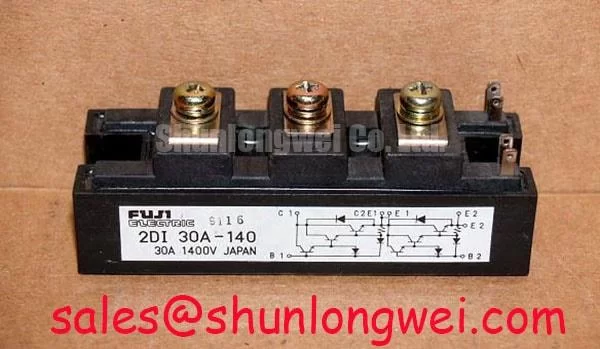
Compare the protective fuse’s total clearing I²t with the semiconductor’s permissible I²t under matching fault conditions, rather than selecting protection from the 30 A rating alone. As a Design Consideration, this comparison must account for prospective fault current, applied voltage, initial device temperature, and the duration covered by the semiconductor surge rating. Fuse coordination reduces fault exposure; it does not establish a guarantee against package rupture.
A useful coordination worksheet separates the evidence needed for each decision. Keep fuse pre-arcing energy distinct from total clearing energy, because current continues flowing during the fuse’s arcing interval.
| Coordination item | Required evidence | Engineering decision |
|---|---|---|
| Semiconductor withstand | Model-specific surge current and I²t limits with test conditions | Establish the applicable short-duration boundary |
| Fuse interruption | Fuse manufacturer’s total clearing I²t and voltage-dependent curves | Compare energy let-through at the expected fault current |
| Mechanical installation | Specified mounting and terminal tightening instructions | Control contact resistance and mounting stress |
Inspect terminal seating and the mounting interface before attributing localized heating to semiconductor damage. As an Engineering Recommendation, use the specified fasteners and tightening sequence, checking that cable loading does not twist the terminals. A generic bolt torque is not a substitute for the module’s assembly instructions, and pressure-contact or double-sided cooling procedures should not be applied without an applicable package drawing.
For replacement assessment, compare 2DI100D-100 against the original circuit requirements through its own datasheet. Similar naming does not establish interchangeable terminal assignments, surge behavior, mounting geometry, or thermal performance.
Preventing Spurious Faults: Reverse Recovery Charge Temperature Coeffi Guidelines for 2DI30A-120
Capture diode current and terminal voltage during the actual commutation interval when investigating unexplained protection trips. As a Design Consideration, reverse-recovery charge, peak recovery current, and recovery time depend on operating conditions, including forward current, junction temperature, and imposed current slope. A cold multimeter measurement cannot characterize those switching effects.
For static screening, compare forward-direction readings with a known-good reference using the same instrument, connection arrangement, and stabilized temperature. Record reverse-direction behavior separately. Unexpected conduction in both directions warrants further isolation of surrounding circuitry; it does not by itself identify a particular internal failure mechanism.
💡 Bench Tip: Use appropriate ESD precautions and identical lead polarity when comparing isolated modules against a known-good cold-state reference.
Recovery time alone does not establish soft recovery. Inspect the current decay and associated voltage overshoot together, taking probe placement and measurement bandwidth into account. Minimize unnecessary commutation-loop area to limit inductive overshoot, with final layout and suppression choices determined by measured system behavior.
The Shindengen power semiconductor and diode resources provide broader device context, not Fuji-specific ratings. Likewise, TVS diode surge-protection principles describe voltage clamping; a clamp must be assessed separately for energy, repetitive operation, and circuit placement rather than treated as a substitute for fuse coordination.
Preventing Spurious Faults: Pulse-Transformer Isolated Firing Circuit Guidelines for 2DI30A-120
Separate the diode module’s power-terminal checks from any pulse-transformer firing circuit serving neighboring controlled devices. A diode conducts according to applied polarity; thyristor gate pulse rise time, holding current, negative gate bias, and multi-pulse firing are not specifications that can be assigned to this product from its diode-module designation.
When evaluating compatibility within a grid-tied static var compensator or thyristor-switched capacitor assembly, trace the module’s actual circuit role before selecting a replacement. As a Design Consideration, firing-circuit measurements belong to the controlled device and its driver, while diode inspection addresses conduction polarity, thermal mounting, and commutation stress. Review 2DI150MA-050 separately if it appears elsewhere in the power-stage documentation; its presence does not establish shared drive requirements or interchangeability.
Keep terminal-to-terminal blocking voltage separate from terminal-to-base insulation withstand. The 1200 V rating is not an authorization to apply that voltage during an insulation test. Use the specified test points and procedure, and inspect external clearance paths for contamination or damaged insulating hardware. The Power Electronics Masterclass offers broader system-reliability context; acceptance records should retain the actual measurement conditions, mounting checks, and circuit-specific protection evidence.