Content last revised on October 6, 2026
2MBI200TA-060 Operational Boundaries: Evaluating Active Miller Clamp Implementation Limits
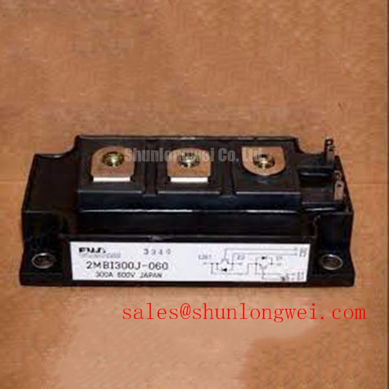
With the DC link isolated and discharged, check the cold-state resistance across the power terminals of the 2MBI200TA-060 before reconnecting a failed drive. Record the readings, inspect the Module case and terminal fasteners, and compare the installed part against the equipment schematic. Fuji Electric identifies this IGBT module with a 600 V voltage rating and a 200 A current rating (Official Specification). Those ratings establish an initial replacement boundary, not proof that another module will fit the terminals, gate drive, cooling assembly, or switching duty.
During turn-off, a rapid voltage change across one switch can couple through its gate-to-collector capacitance and raise the gate voltage. In a drive with complementary switching devices, the resulting unintended turn-on can create cross-conduction. This is a gate-drive integration issue rather than a separate rating of the 2MBI200TA-060. As a Design Consideration, an active Miller clamp offers a low-impedance path near the gate when the driver commands the device off. Its effectiveness depends on clamp timing, the gate-loop layout, and the actual switching waveform.
Before changing a clamp circuit, trace the installed driver schematic. Confirm where the driver senses gate voltage, whether the clamp is active during the vulnerable interval, and how the return path reaches the module terminal. Keep the gate and return paths compact and separated from high-current switching paths; determine electrical clearances from the equipment’s insulation design, not from an assumed clearance for this module. Negative gate bias is another possible system-level measure, but its value must be checked against the original module documentation and driver limits rather than prescribed from the voltage and current ratings alone.
For a drive-board fault, compare the off-state gate waveform with a known-good channel using an appropriately isolated measurement setup. Look for gate-voltage excursions coincident with opposite-switch transitions, then examine driver supply stability, clamp behavior, and the optocoupler or digital isolator’s specified common-mode transient immunity. A disturbance at an isolator output does not, by itself, establish that the IGBT has failed. The broader protection and measurement context is covered in the Power Electronics Masterclass.
2MBI200TA-060 Thermal-Electrical Optimization: Practical Junction-to-Case Assessment
A 200 A rating (Official Specification) cannot be treated as permission for an arbitrary pulsed overload. If the equipment uses the module in a regenerative-braking chopper or bidirectional battery converter, obtain the applicable switching-loss, junction-temperature, and transient thermal-impedance data from the correct Fuji Electric documentation before estimating peak junction temperature. An Engineering Calculation can apply a verified multi-RC thermal model to the measured loss pulse and initial case temperature; without those model coefficients, a numerical peak-temperature margin would be invented.
On the bench, capture current, switching voltage, pulse duration, and case-temperature conditions for the actual duty cycle. Compare repeated pulses with the available cooling interval, especially where braking-resistor energy absorption or battery charge and discharge produces uneven thermal loading. After a surge event, inspect the associated diode and current path as well as the IGBT. No diode surge-current or ITSM limit has been supplied here, so neither surge survival nor a safe junction-temperature recovery window can be inferred from the module’s 200 A rating.
If the high-side driver relies on a bootstrap supply, its capacitor must support gate-charge demand, driver quiescent consumption, and leakage over the longest interval without recharge. That is a Design Consideration for the installed driver circuit, not a capacitor specification for the module. Verify the high-side supply at the driver during the actual switching sequence before attributing an intermittent turn-on problem to the power module.
Assembly Integrity and Layout: Assessing Current Distribution for 2MBI200TA-060
For a module replacement, compare the original footprint, terminal positions, mounting interface, and circuit topology before applying power. A matching 600 V and 200 A label does not establish mechanical or dynamic interchangeability. The 2MBI200PB-140 can be included in a cross-model review, but its ratings, terminal arrangement, diode configuration, and gate-drive requirements require independent verification against the original equipment documentation.
Where a system parallels switching paths, static current sharing depends in part on their conduction characteristics at operating temperature. A positive temperature coefficient of on-state voltage can assist sharing under the conditions shown in a device’s characterization data; it should not be assumed for every current and temperature point of this module. Dynamic sharing also depends on matched gate-drive paths and comparable power-loop impedance. Check physical routing and connections, then assess switching currents under controlled conditions rather than relying on a cold resistance match.
Clean the mounting surfaces and inspect for damage that could prevent even contact. Follow the equipment and module mounting instructions for fastener sequence, torque, and thermal-interface application; neither a bolt size nor a tightening torque is established by the supplied ratings. Field alert: Do not tighten the module against an uneven heatsink surface to compensate for poor contact. Electric forklift traction equipment is one possible compatibility-evaluation context, but its battery voltage, enclosure, cooling, and drive topology must be checked before treating this part as a replacement.
Benchtop Waveform Tuning: Checking Reflected-Voltage Stress with 2MBI200TA-060
Long leads between a switched drive output and a motor can produce reflected-wave voltage at the motor terminals. Under particular impedance and edge-time conditions, the terminal peak can approach twice the launched voltage; that is a transmission-line effect, not an additional withstand rating for the 2MBI200TA-060. Measure at the relevant terminals with suitable probes while checking the module’s switching-voltage peak against its 600 V rating (Official Specification). Do not substitute a DC-link reading for the peak observed during switching.
If the waveform shows excessive overshoot or ringing, compare cable length, termination, output-filter arrangement, and gate-drive settings with the original equipment design. A dv/dt filter or output choke is a system option whose selection depends on motor insulation, cable characteristics, operating current, and measured waveforms; its size cannot be prescribed from the module model number. Keep the DC-link commutation loop compact to reduce inductive overshoot at turn-off, and verify the resulting peak under the equipment’s operating conditions.
Topology matters when reviewing braking and reverse-current behavior. Fuji Electric’s Brake Chopper IGBT Modules and RC-IGBT Modules describe distinct product families; neither reference establishes the internal configuration of the 2MBI200TA-060. Check its documented circuit diagram against the installed braking or traction-drive circuit before interpreting diode-current waveforms or changing suppression hardware.