
Content last revised on September 10, 2026
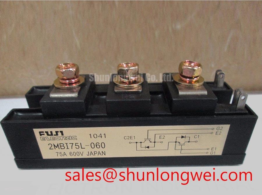
Expert Technical Analysis: The Fuji Electric 2MBI75L-060 IGBT Module
Engineers and procurement specialists often inquire whether a legacy 600V IGBT can still meet the rigorous efficiency demands of modern industrial hardware. The 2MBI75L-060, a dual IGBT module from Fuji Electric's established L-series, provides a definitive answer through its optimized balance of switching speed and conduction efficiency. Designed specifically for high-frequency power conversion, this 600V | 75A module serves as a reliable building block for motor drives and uninterruptible power systems.
Frequently Asked Questions
Optimizing Design Performance and Thermal Reliability
How does the Vce(sat) of 2.8V at 75A specifically impact the thermal management strategy for this module?
The collector-emitter saturation voltage (Vce(sat)) of 2.8V is a critical indicator of conduction losses. In a 75A application, this translates to significant heat generation during the "on" state. Engineers must ensure that the thermal resistance from junction to case (Rth(j-c)), typically 0.25 °C/W for this series, is accounted for by selecting a high-performance heatsink. Effective Thermal Management is essential to keep the junction temperature within the safe operating limit of 150°C, especially in high-density Variable Frequency Drive (VFD) enclosures.
What are the primary benefits of the high-speed switching characteristics in 20kHz inverter stages?
The 2MBI75L-060 is engineered for high-frequency operation, featuring a typical fall time (tf) of 0.30µs. In a 20kHz switching environment, this rapid transition minimizes Switching Loss, which is the energy dissipated during the interval between the on and off states. By reducing this "switching tax," the module allows for smaller magnetic components and improved overall system efficiency in UPS (Uninterruptible Power Supply) designs.
Key Parameter Overview
Decoding the Specs for Enhanced Switching Reliability
| Technical Specification | Official Rating / Value | Engineering Significance |
|---|---|---|
| Collector-Emitter Voltage (Vces) | 600V | Provides necessary headroom for 240V/380V AC line rectified DC buses. |
| Continuous Collector Current (Ic) | 75A (at Tc=25°C) | Defines the steady-state current handling for medium-power motor control. |
| Pulsed Collector Current (Icp) | 150A | Crucial for handling Motor Drive startup surges and inductive kickback. |
| Isolation Voltage (Visol) | 2000V AC (1 minute) | Ensures safety and signal integrity between power stages and control logic. |
| Switching Time (ton) | 1.20µs (Max) | Determines the maximum PWM frequency achievable without excessive loss. |
For detailed timing charts and safe operating area curves, engineers should Download the 2MBI75L-060 datasheet for detailed specifications and performance curves.
Technical Deep Dive
Architecture and Losses in High-Frequency Topologies
The internal architecture of the 2MBI75L-060 utilizes a non-punch-through (NPT) or similar planar technology characteristic of the L-series, which provides a positive temperature coefficient for Vce(sat). This is particularly advantageous when IGBT Paralleling is required, as the module naturally balances current among devices. To visualize this, think of the Vce(sat) as the narrowness of a pipe; as the device heats up, the "pipe" slightly constricts, encouraging current to flow through cooler, less resistive parallel paths, thus preventing thermal runaway.
Furthermore, the inclusion of a high-speed Free Wheeling Diode (FWD) with optimized reverse recovery characteristics is vital. During the "off" command, the FWD handles the inductive freewheeling current. The 2MBI75L-060 minimizes the reverse recovery current (Irr), which in turn reduces the electromagnetic interference (EMI) often associated with hard-switching topologies. For systems requiring even higher voltage thresholds, the 2MBI200NB-120 offers a Vces of 1200V.
Application Scenarios & Value
Achieving System-Level Benefits in Industrial Motion Control
In the context of an AC/DC Servo Drive, the 2MBI75L-060 excels due to its robust SOA (Safe Operating Area). When managing a robotic arm's rapid acceleration, the module must withstand peak currents that exceed its nominal 75A rating. The 150A pulsed current rating ensures the module can handle the transient torque demands without degradation.
Beyond motor control, this module is a staple in high-performance Solar Inverters and welding power supplies. Its compact 2-pack configuration simplifies the layout of full-bridge or three-phase bridge circuits. Designers can find further insights on optimizing these configurations in our guide on In-Depth Analysis of IGBT Modules. For applications prioritizing maximum power density in smaller footprints, the 7MBR50SA060 provides a highly integrated alternative.
Further Engineering Considerations
Refining Design Implementation
What is the recommended Gate Drive voltage for the 2MBI75L-060?
To achieve the rated Vce(sat) and ensure fully saturated operation, a Gate Drive voltage (Vge) of +15V is standard. Using a lower voltage can significantly increase conduction losses and risk operating in the linear region, leading to catastrophic failure.
How does the mounting torque affect the long-term reliability of the M232 package?
Maintaining a consistent mounting torque (typically 3.5 N·m for the terminals and baseplate) is critical to ensure uniform pressure on the Thermal Interface Material (TIM). Improper torque can lead to microscopic air gaps, drastically increasing the effective Thermal Resistance and causing localized hotspots.
Can the 2MBI75L-060 handle short-circuit conditions?
Yes, the module is designed with a Short-Circuit Withstand Time (typically 10µs). However, this requires the gate driver to implement rapid desaturation detection to shut down the module before it exceeds its thermal limits. For more on protection, see our resource on Ensuring IGBT Reliability.
From an engineering perspective, the 2MBI75L-060 represents a mature, predictable solution for power stages where switching agility is as important as raw current capacity. Its integration into a system should be preceded by a thorough analysis of the switching trajectories and heat dissipation paths to ensure a 20-year service life in industrial environments.