Content last revised on October 24, 2026
Transient Dynamics & Electrical Design: Pollution Degree 3 Creepage Distances on 1DI50H-120
With the DC link isolated and its discharge verified, inspect the 1DI50H-120 terminal surfaces, mounting face, and surrounding insulation for dust tracks, moisture, and heat discoloration before reconnecting the power stage. Record the original terminal connections before removal; replacement decisions depend on circuit configuration as well as electrical ratings.
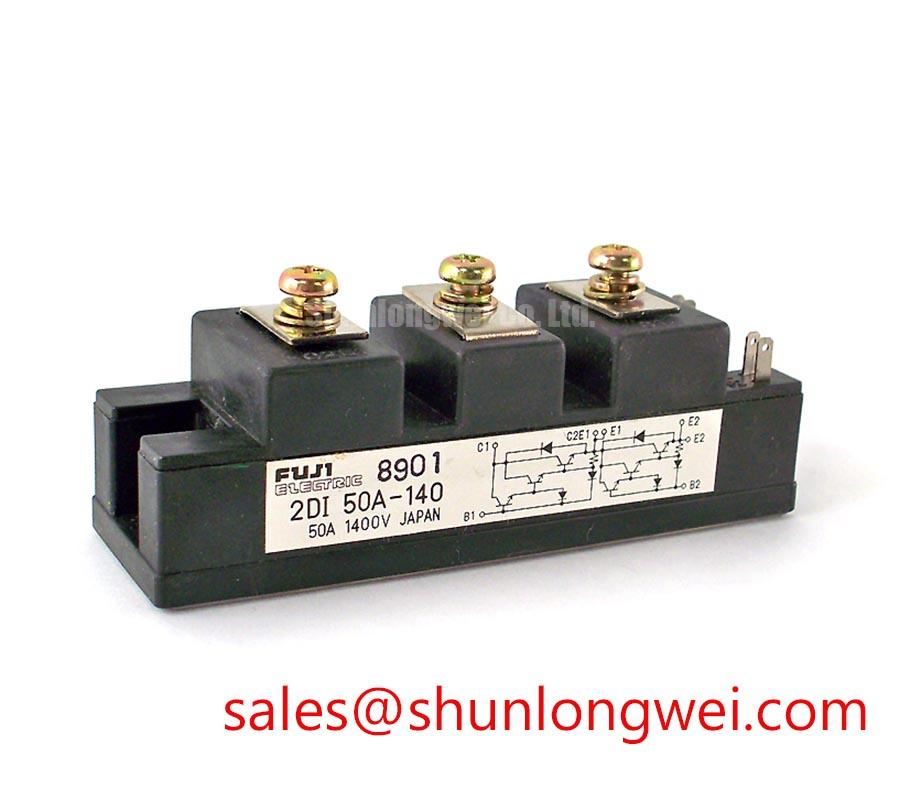
The Fuji Electric 1DI50H-120 has a collector-emitter voltage rating of 1200 V, collector current rating of 50 A, and gate-emitter voltage limit of ±20 V (Official Specification). Its supplied configuration is a single IGBT with an integrated freewheeling diode. Low saturation voltage and high-speed switching are qualitative characteristics, not numerical loss specifications.
Remove conductive deposits around the terminals before evaluating insulation condition. As a Design Consideration, pollution degree classification belongs to the equipment insulation assessment; it does not establish a certified creepage distance for this module. Required spacing depends on working voltage, insulating material, contamination, and the applicable equipment standard.
For terminal-to-baseplate insulation testing, use the equipment-approved procedure with sensitive circuitry disconnected and the specified terminals grouped correctly. Neither a test voltage nor an acceptance resistance should be assigned from a generic maintenance rule. Surface leakage measurements also cannot identify the module’s internal substrate material or independently prove internal ceramic integrity. Investigate contamination and condensation before interpreting an abnormal result.
During switching evaluation, minimize the commutation-loop area through closely coupled outgoing and return conductors where the assembly permits. This Design Consideration reduces inductive turn-off overshoot; evaluate collector-emitter peaks against the 1200 V rating under representative operating conditions. Fuji Electric High-Speed Discrete IGBTs provides manufacturer context for switching-device behavior, rather than model-specific insulation approval.
1DI50H-120 Circuit Protection & Reliability: Calibrating Sizing Braking Resistors and Chopper Transistor
Trace the DC-link energy path before assigning the module a braking function. Where a system includes regenerative motor deceleration, the chopper and resistor must accommodate returned energy, repetition rate, and thermal recovery. The resistor dissipates energy drawn from the DC link; the transistor controls that current. These are system-level Design Considerations, not additional 1DI50H-120 ratings.
Gate-driver source and sink capability should be evaluated against gate charge, the intended switching transition, and measured ringing. External gate resistance trades switching speed against oscillation and dissipation. Miller-induced gate movement depends on collector-gate capacitance and voltage slew rate; Miller plateau charge and reverse-transfer capacitance are related quantities, not interchangeable specifications. Evaluate active clamping through the driver’s operating limits and measured fault response rather than assuming it is built into this module.
For procurement comparison, 6DI50AH-050 belongs in a separate compatibility review, not an automatic replacement decision.
| Selection item | 1DI50H-120 | 6DI50AH-050 |
|---|---|---|
| Manufacturer | Fuji Electric | Consult datasheet |
| Collector-emitter rating | 1200 V, Official Specification | Consult datasheet |
| Collector current rating | 50 A, Official Specification | Consult datasheet |
| Configuration | Single IGBT with integrated FWD | Confirm circuit and terminal arrangement |
| Replacement assessment | Compare drive requirements, switching behavior, mounting dimensions, and cooling interfaces. | |
When assessing compatibility with industrial inverter welders or medium-frequency induction-heating supplies, identify each device’s actual circuit role. A separate module such as 1DI300D-100 requires its own topology review. Where an upstream phase-controlled rectifier exists, firing-angle operation and line harmonics belong to that input-stage assessment, not to the switching module’s specifications.
Preventing Spurious Faults: Auxiliary Kelvin Emitter vs Main Power EMI Guidelines for 1DI50H-120
Identify the emitter connections from the terminal drawing before routing the gate-driver return. A dedicated auxiliary Kelvin emitter connection is not established by the supplied specifications; do not assign that function to an unidentified terminal.
As a Design Consideration, keep the driver return closely associated with the gate conductor and separate it from load-current routing wherever the documented connection arrangement permits. Shared emitter-path inductance can shift the apparent gate-emitter voltage during rapid current changes. Observe the voltage at the device connection using appropriately rated differential measurement equipment, rather than relying exclusively on the driver-board waveform.
Investigate intermittent trips alongside connector condition, driver supply behavior, and switching-node coupling. Correlated waveforms help distinguish actual gate disturbance from measurement pickup. The ±20 V gate-emitter limit is an electrical boundary, not a recommended drive setting.
Assembly Integrity & Layout Architecture: Baseplate Flatness and Screw-Tightening Guidelines for 1DI50H-120
Clean the heatsink contact surface and inspect flatness before applying thermal interface material. As an Engineering Recommendation, select application thickness from the interface material instructions and module mounting requirements; an assumed universal film thickness can leave voids or excessive thermal resistance.
Do not attempt to flatten suspected baseplate curvature through additional screw torque. Follow the specified tightening sequence and fastener requirements, checking that mounting hardware does not introduce uneven loading. After thermal stabilization, compare temperature trends at consistent load and ambient conditions.
Maintenance Note: Regularly check terminal temperature trends and cooling airflow, and schedule cleaning or interface inspection when those trends deteriorate.
Set inspection intervals from cabinet dust loading, operating hours, and thermal history. Check moisture exposure after cold shutdowns before re-energizing. For broader technology context, Unlocking Efficiency in Industrial Drives discusses a different IGBT technology generation; it does not establish this module’s construction or lifetime. Use Fuji Electric’s power semiconductor resources alongside the equipment service procedure when defining acceptance checks.