

Content last revised on September 23, 2026
Benchtop Waveform Tuning: Mitigating Stress via Thermal Interface Material Thickness Uniformity on 6DI50AH-050
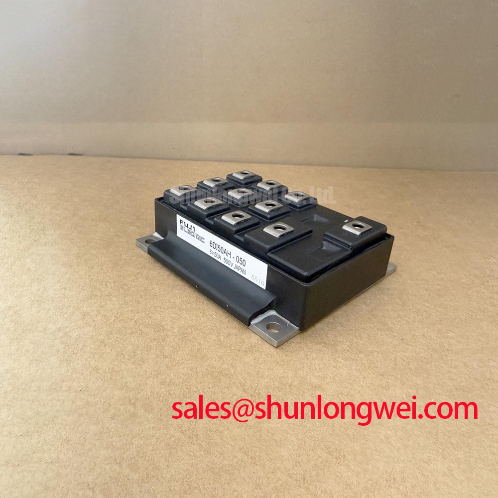
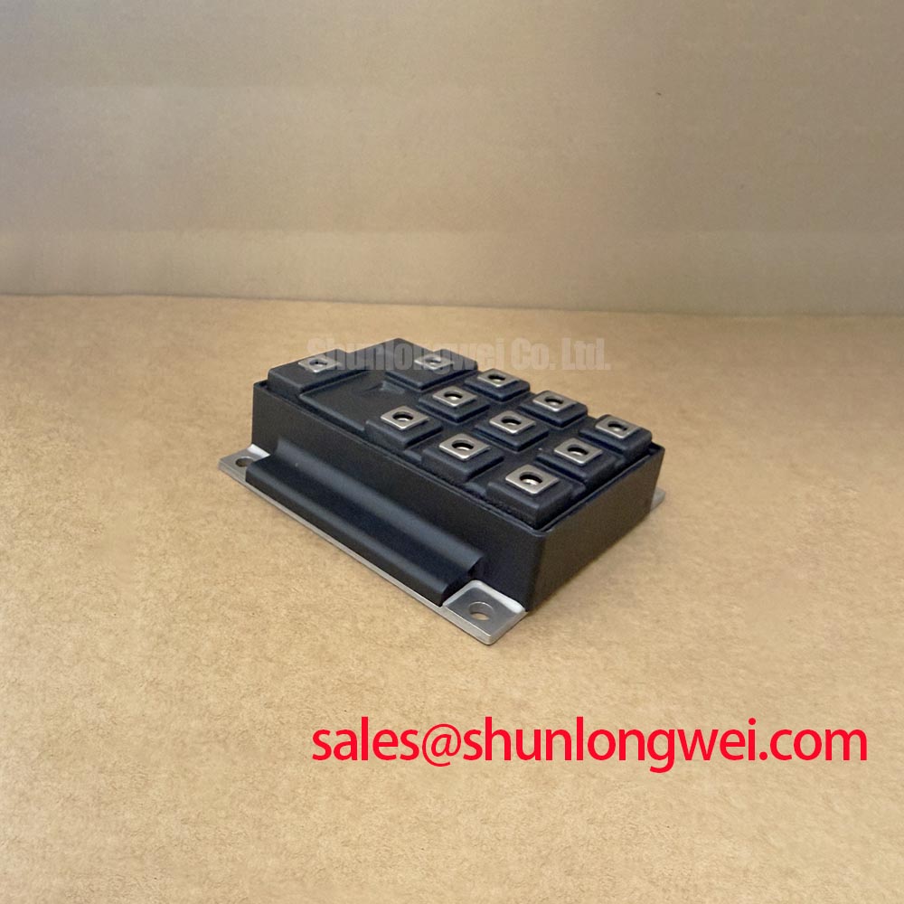
Before fitting the replacement, isolate the DC link, inspect the power terminals and case for mechanical damage, and compare the equipment nameplate boundary with the 6DI50AH-050 marking. This Fuji Electric power transistor module is officially rated at 600.0 V and 50.0 A, with a Power Transistor Module package classification. Confirm the original circuit topology, terminal assignment, gate-drive arrangement, and cooling interface from the equipment documentation before energizing the assembly.
| Parameter | Official Specification |
|---|---|
| Manufacturer | Fuji Electric |
| Part Number | 6DI50AH-050 |
| Rated Voltage | 600.0 V |
| Rated Current | 50.0 A |
| Package Classification | Power Transistor Module |
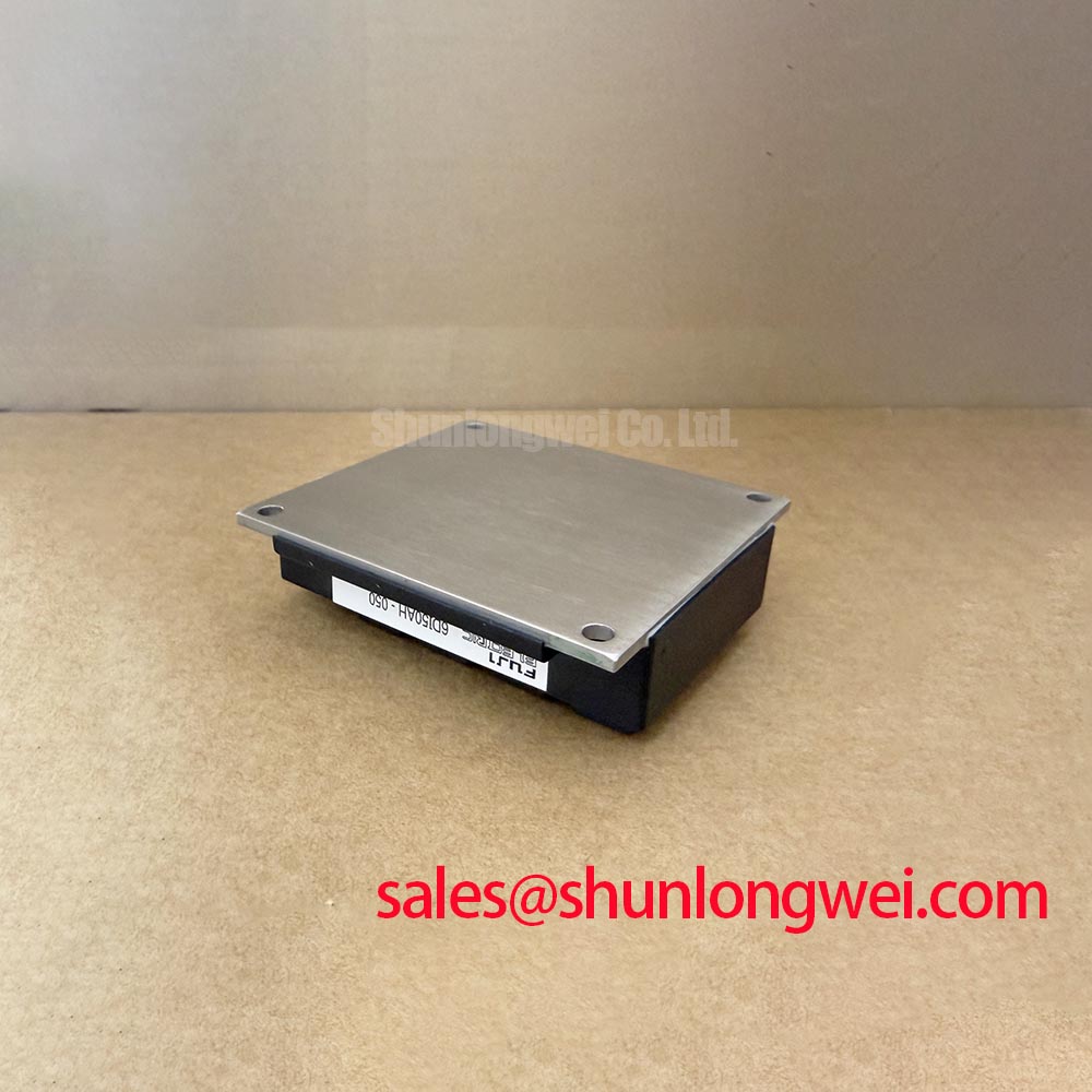
Start with the heatsink plane rather than the gate-drive board. A clean, flat mounting face is essential because an uneven thermal interface can create localized case temperature differences that do not appear immediately during a short bench run. As a Design Consideration, thermal interface material is commonly controlled within a thin, uniform film, often discussed around 50 to 100 μm where the selected material and mounting system support that range. The actual thickness must follow the thermal material supplier’s instructions and the mechanical constraints of the installed equipment.
Apply the interface material evenly, remove visible debris from both mating surfaces, and tighten mounting screws in a crosswise sequence so the module seats progressively across the heatsink. If baseplate flatness or heatsink curvature is suspected, inspect contact transfer after removal rather than compensating with an excessive layer of compound. A thicker layer can mask a mechanical problem while increasing thermal resistance.
⚠️ Field Alert: Disconnect and discharge the DC link before removing gate or power connections, and tighten all mounting hardware only to the equipment manufacturer’s specified torque.
During waveform tuning, compare switching traces, case temperature rise, and load current against a known stable channel where available. Thermal behavior that changes after repeated load cycling can point to mounting contact, airflow, drive timing, or load conditions; it should not be assigned to one cause without measurement. Fuji Electric’s power semiconductor product information is a useful manufacturer reference when confirming the applicable module family documentation.
Preventing Spurious Faults: DC-DC Converter Interleaving and Ripple Current Guidelines for 6DI50AH-050
In commercial string inverter and micro-grid energy-storage equipment, battery-side converters and inverter DC links can exchange power in either direction. Under peak-shaving or rapid charge and discharge transitions, the resulting current ripple and thermal cycling are determined by the complete converter topology, control method, busbar geometry, capacitors, battery impedance, and switching conditions. The 600.0 V, 50.0 A ratings are Official Specifications for this module, not a complete system-duty approval.
As a Design Consideration, inspect the DC-link capacitor condition, laminated or busbar joints, fuse connections, and return paths before changing the semiconductor module. Interleaved converter phases require phase-current sharing to be assessed at operating load. Do not assume static current sharing proves dynamic sharing, particularly where individual drive paths, current sensors, or power-loop impedances differ.
High-speed semiconductor fuse coordination also requires verification against the installed fuse documentation, fault-clearing characteristics, prospective fault current, and the module’s applicable surge information. This is a system-level protection exercise, not a value that can be prescribed from the module’s voltage and current ratings alone. For broader test sequencing and evidence-based troubleshooting practices, refer to the Field Engineer’s Handbook.
Field Diagnostics & Commissioning: Transient Thermal Impedance in 6DI50AH-050 Topologies
At commissioning, measure cold-state terminal relationships only after all stored energy has been safely discharged and the module is electrically separated as required by the service procedure. A multimeter check can identify an obvious short or an unexpected conductive path, but it cannot validate switching performance, insulation condition under operating stress, or junction-temperature margin.
For pulsed overload assessment, the junction-to-case thermal response must come from applicable manufacturer thermal data for the exact device and operating condition. An Engineering Calculation can use a validated multi-RC thermal model with measured pulse power, pulse duration, initial case temperature, and repetition pattern to estimate peak junction temperature. Without the correct thermal-impedance curve and switching-loss information, assigning a numerical junction margin would be unsupported.
Practical commissioning should therefore combine power-up checks with controlled waveform capture, current observation, protective-trip verification, and thermal stabilization under the actual load profile. Repeated nuisance trips may involve excessive current ripple, gate-loop disturbance, sensor scaling, cooling performance, or control timing. Compare the affected phase with a known-good signal path before replacing related assemblies.
Transient Dynamics & Electrical Design: PCB Gate Loop Layout Symmetry on 6DI50AH-050
Keep each gate-drive path compact and consistent between parallel or phase-related positions. The gate command and its return path should travel together so inductive coupling is minimized during high current transitions. Where the confirmed module terminal diagram provides an auxiliary emitter or dedicated drive-return terminal, route that return separately from the main high-current emitter path. This Design Consideration helps reduce common-mode ground movement at the driver reference.
Negative gate bias, gate resistance, clamp arrangement, desaturation protection, and controller dead time must be verified from the original driver design and the applicable Fuji Electric documentation. These values cannot be safely transferred from another module or inverter platform simply because the voltage and current ratings appear similar. Oscilloscope measurements should verify turn-on and turn-off behavior at the installed DC-link voltage and operating current.
When evaluating another module for a repair review, compare terminal layout, topology, voltage class, current class, thermal interface, and driver compatibility rather than relying on package appearance. The QM200HA-HK can be reviewed as a separate power-module reference, but its suitability remains dependent on the original circuit and mechanical requirements. Additional regional power-electronics information is available from Fuji Electric Europe.