



Content last revised on September 30, 2026
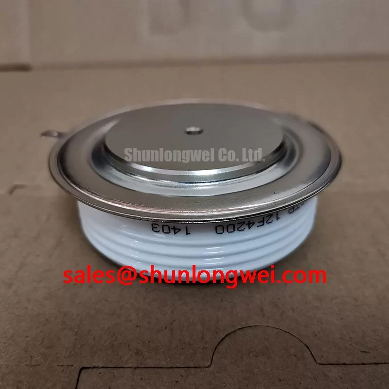
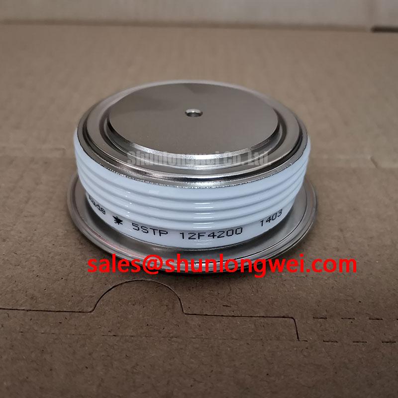
Field Diagnostics and Commissioning: Firing Angle in 5STP-12F4200 Topologies
Capture the voltage across the thyristor and its gate pulse during a commanded firing event, then compare their timing with the controller’s phase reference. In a phase-controlled rectifier, delaying the firing angle changes the average output voltage and the input-current waveform; the effect on power factor and reactive demand must be assessed at the equipment level. Do not infer an allowable firing-angle range from the 5STP-12F4200 part number.
Trace the installed circuit before testing. A thyristor-switched capacitor branch in a grid-tied static var compensator has different switching objectives from a controlled rectifier, even if both use thyristors. Check the controller command, gate-pulse delivery, terminal identification and current waveform against the equipment schematic. The supplied product information gives no numerical voltage or current rating, gate-trigger limits, terminal diagram, mounting torque or fuse coordination data. Obtain those values from the applicable manufacturer documentation before approving an operating margin or replacement.
For a cross-model assessment, 5STP04D4000132 can be evaluated against the installed device’s verified ratings, mechanical interface and gate-drive requirements; the similar naming alone does not establish interchangeability. Where a topology includes a separate auxiliary or upstream stage, assess SSIL2890S46C by its own documented role rather than treating it as part of the thyristor assembly.
5STP-12F4200 Thermal and Electrical Assessment: Commutation Behavior
Probe the commutation interval when heating or switching noise rises, looking for current overlap, voltage overshoot and a change in waveform shape as operating temperature changes. Reverse-recovery peak current and recovery time describe diode behavior; they should not be presented as unverified 5STP-12F4200 specifications. If an associated freewheel or rectifier diode is present, assess its recovery from that device’s documentation and measured circuit waveforms.
Compare measured current and case-temperature trends with the verified thyristor limits under the actual cooling arrangement. Inspect the mounting interface for even contact and check terminal and mounting fasteners against the specified assembly procedure. The supplied information contains no thermal resistance, permitted torque or thermal-interface-material thickness, so none can be assigned to this model here. 💡 Pro Tip: Keep the gate and return paths close together to reduce coupled noise, then verify reliable firing at the measured operating extremes.
When reviewing a separate diode stage, the Shindengen power semiconductor range and Mitsubishi Electric diode module lineup provide device-category context, not substitute ratings for this ABB part.
Field Diagnostics and Commissioning: Surge Protection in 5STP-12F4200 Circuits
Record the peak voltage at the thyristor terminals during the switching event that triggers a protection alarm. Compare it with the voltage recorded at the supply and across the existing protective components; this helps distinguish an incoming disturbance from an overshoot generated within the equipment. Examine the installed MOV and RC snubber for visible damage and confirm their connections against the circuit drawing.
Design Consideration: MOV clamping level and snubber behavior should be evaluated against the equipment’s surge environment, normal waveform and verified thyristor voltage limits. IEC 61000-4-5 is a system surge-test reference, not proof that an individual thyristor meets an equipment immunity requirement. The numerical voltage rating and surge-current capability of 5STP-12F4200 are not present in the supplied parameters, so protection coordination cannot be established from this page. For broader switching-margin test considerations, see the Power Electronics Masterclass.
5STP-12F4200 Practical Tuning: Unintended Turn-On and Current Rise
Compare the gate-to-cathode waveform with the voltage across the thyristor when conduction appears earlier than commanded. Noise on the gate path, a steep reapplied voltage and the controller’s firing sequence are distinct possibilities; test them separately rather than assigning one cause from a single trace. Confirm the gate and cathode terminal connections using the correct device drawing before attaching a probe or changing the drive circuit.
Design Consideration: An RC snubber can moderate reapplied-voltage transients, while circuit inductance or a series reactor can influence the rate of current rise at turn-on. Their values depend on the measured network, operating duty and the verified device limits. Check gate-trigger current and voltage requirements and pulse-train behavior against the manufacturer’s data, then validate reliable firing and acceptable current rise across the equipment’s operating range. Do not transfer gate-drive, snubber or fuse settings from another thyristor solely because its package or application appears similar.