


Content last revised on September 21, 2026
Transient Dynamics & Electrical Design: Gate Trigger Current Dynamics on VS-26MB120A
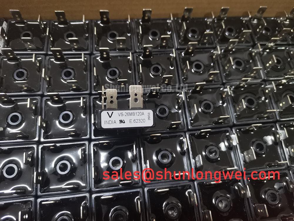
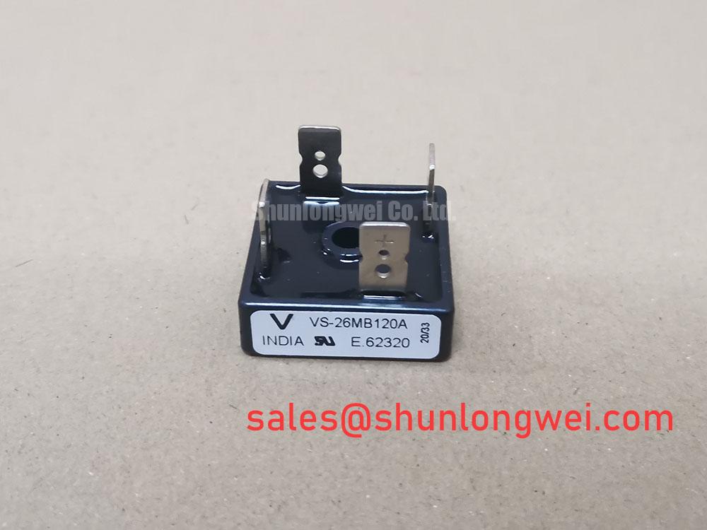
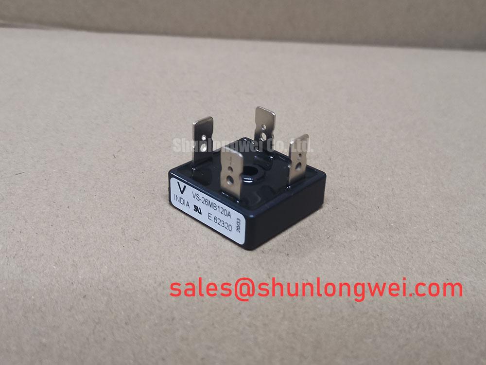
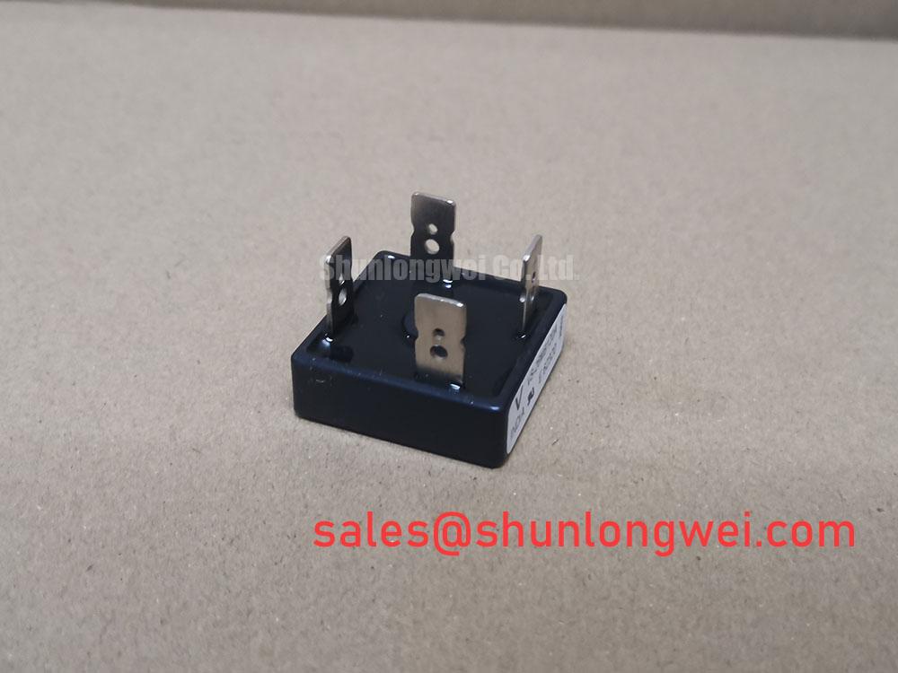
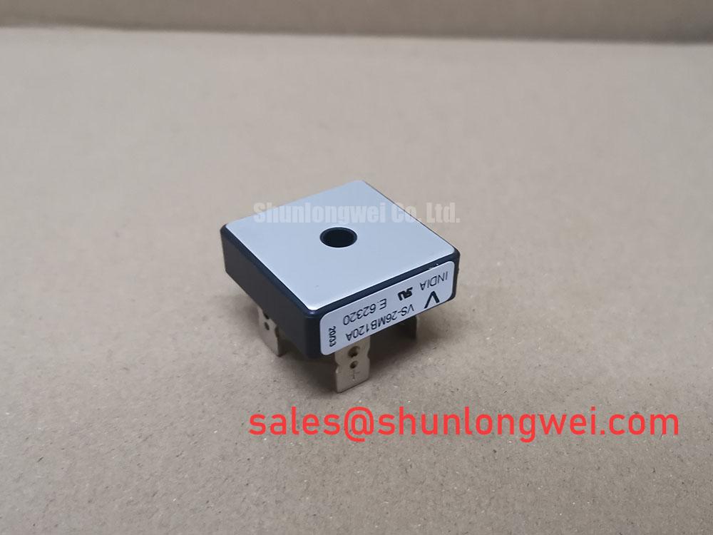
With power isolated and the DC bus discharged, first compare the cold resistance path across the bridge terminals with the removed unit and inspect the Power Block / Bridge Case for cracked insulation, heat discoloration, loose terminal hardware, or a distorted mounting face. The VS-26MB120A is a Vishay thyristor/diode module rated at 1200.0 V and 26.0 A as an Official Datasheet Specification. These three identifiers, together with the terminal arrangement and mechanical fit in the existing assembly, are the starting boundary for a repair evaluation.
| Parameter | Value | Classification |
|---|---|---|
| Manufacturer | Vishay | Official product identification |
| Model | VS-26MB120A | Official product identification |
| Rated voltage | 1200.0 V | Official Datasheet Specification |
| Rated current | 26.0 A | Official Datasheet Specification |
| Case style | Power Block / Bridge Case | Official Datasheet Specification |
Before reconnecting a replacement module in a high voltage three phase motor solid state soft starter, identify every terminal from the original equipment wiring record rather than relying on cable position alone. The available official identification confirms voltage, current, and case style, but it does not establish gate trigger current, gate pulse rise time, holding current, or a firing sequence for this specific listing. Those values must be verified from the original Vishay documentation and the equipment schematic before any gate drive measurement or adjustment is attempted.
This distinction matters during an urgent field repair. A control board can produce unstable phase control because of an optocoupler path, isolated driver supply, connector issue, or timing reference fault; it cannot be diagnosed safely by assigning a universal gate current to the module. Where the installed circuit has control terminals, compare all phase firing waveforms with a known healthy channel and check that the driver reference is measured from the correct local return. Design Consideration: preserve short, secure control connections where the equipment topology requires them, since unwanted coupled transients can interfere with low energy control signals.
Inspect the existing semiconductor fuse documentation and coordination data held by the machine builder. Fuse clearing energy, the protected semiconductor’s surge limits, conductor cross section, and available fault current are system dependent. No fuse I²t value or firing pulse prescription should be transferred from a different module without manufacturer documentation and a verified coordination study.
⚠️ Field Alert: Tighten electrical and heatsink hardware only to the torque specified by the original equipment documentation, with a clean flat mounting surface and an even thin thermal interface layer.
Transient Dynamics & Electrical Design: Turn-On Current Rise Limiting for VS-26MB120A
A replacement assessment should confirm that the installed module is operating within its 1200.0 V and 26.0 A official ratings under the actual circuit conditions, not only under idle meter checks. In a three phase soft starter, phase angle control, motor cable inductance, line disturbances, bypass contactor timing, and the motor load all influence turn on stress. Capture voltage and current at the equipment’s approved test points using appropriately rated instruments, then compare phase behavior rather than interpreting one waveform in isolation.
RC snubbers and series saturable reactors, where present in the original design, are part of the surrounding assembly rather than published attributes of the VS-26MB120A. Design Consideration: retain the original suppression network while investigating abnormal voltage rise or unequal current sharing, because removing or arbitrarily changing those parts can alter transient behavior. The system engineer should validate peak voltage margin against the DC link or line voltage during switching tests and should verify the actual thermal duty of the replacement assembly.
For repair teams reviewing alternative power technologies, Vishay’s Vishay Siliconix Industrial Power MOSFETs resource helps distinguish MOSFET switching considerations from the characteristics of a bridge power module. It is not evidence of electrical interchangeability. When a hardware alternative is being reviewed, VS-ST730C18L0 should be compared objectively against the original circuit’s voltage class, current duty, terminal layout, mounting arrangement, and control topology before any substitution decision.
VS-26MB120A Thermal Electrical Optimization: Semiconductor Protection Fuse Selection in Practical Tuning
Thermal evidence should be collected before a module is blamed for a shutdown. Check heatsink flatness, cooling path condition, terminal tightness, adjacent fuse condition, and signs of overheating on busbars or cable lugs. A hot connection can create a local voltage drop and asymmetric phase behavior that resembles a semiconductor problem. Likewise, a bypass contactor that does not close cleanly can leave the starter conducting longer than the expected start interval.
Engineering Recommendation: select and coordinate semiconductor protection from the original equipment fault study, using the fuse manufacturer’s time current and I²t documentation together with the semiconductor manufacturer’s applicable surge and fault capability data. The available product information does not provide a VS-26MB120A fuse I²t coordination table, so assigning a specific fuse class, clearing energy, or short circuit outcome would not be a valid product specification. Inspect the full phase assembly after a fault, including the driver board and line side connections, before placing a repaired starter back into service.
Where severe line transients or repeated fault events are being investigated, The 1200 V CoolSiC™ MOSFET Advantage in Three-Phase Power Conversion provides a useful reference for examining voltage stress and three phase power conversion test methods. It should be used as technical context only, since the VS-26MB120A remains a distinct Vishay bridge module with its own specified operating boundaries.
Benchtop Waveform Tuning: Mitigating Stress via Thermal Duty Cycle Management of Bypass Contactor on VS-26MB120A
During a controlled restart, review the starter’s programmed ramp, actual motor current trace, and bypass contactor transition as one event. Locked rotor current, load inertia, supply condition, and control settings determine the inrush profile; no universal current reduction target can be assigned to the VS-26MB120A from its voltage and current ratings alone. If the current waveform remains elevated or phases differ materially during the ramp, stop testing and examine control timing, line balance, motor condition, and the bypass circuit before extending the duty cycle.
When integrating this 1200.0 V, 26.0 A Vishay Power Block / Bridge Case module, designers should verify the original thermal interface, enclosure airflow, terminal creepage arrangement, and measured case temperature under the real motor start profile. Repeated starts should be evaluated with adequate cooling recovery determined by the system’s measured temperatures and operating sequence. This keeps the repair decision tied to the actual equipment rather than an assumed application profile.