

Content last revised on September 20, 2026
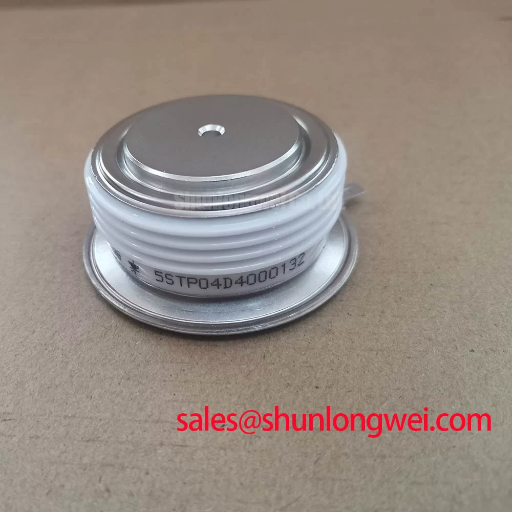
Preventing Spurious Faults: AC Input Transient Overvoltage Clamping Guidelines for 5STP04D4000132
In a high-current rectifier, nuisance shutdowns can begin upstream of the power semiconductor. Incoming AC transients, switching events from adjacent loads, capacitor-bank operations, and transformer energization can all disturb the rectifier supply. For a thyristor topology using the 5STP04D4000132, the protection review should begin with the AC input waveform and the installed suppression network rather than assuming that the module itself is the source of every trip.
Design Consideration: MOV stages and RC snubbers are system-level protection elements. Their selection must be based on the actual AC supply, transformer leakage behavior, surge environment, rectifier topology, and the voltage limits stated in the original ABB technical documentation. A clamp that is incorrectly coordinated can either permit excessive transient stress or absorb repetitive energy beyond its intended duty. The system engineer should review the condition of each suppression component during planned maintenance, especially where heat, dust, humidity, or vibration can alter terminal contact quality.
For installations assessed against surge-immunity requirements, IEC 61000-4-5 is commonly used at equipment level. It does not create an individual device rating for this thyristor module. The complete rectifier cabinet, its wiring arrangement, grounding scheme, incoming protection, and control electronics determine the equipment response.
Fuse coordination should be reviewed as a chain of values rather than as a single part substitution. The semiconductor fuse clearing characteristic, the prospective fault current, conductor resistance, transformer impedance, and the module’s manufacturer-defined surge and I²t limits must be checked together. No I²t withstand value is stated in the provided official product data for this specific module; therefore, technicians should obtain it from the applicable ABB documentation before approving a fuse change.
Terminal connections deserve equal attention. Clean mating surfaces, correct hardware, and a documented tightening procedure reduce variable contact resistance. Mounting torque is not supplied in the available official parameters for the 5STP04D4000132, so it should not be inferred from another HiPak part or applied from a generic table. Use the torque requirement specified for the exact module and hardware stack.
⚠️ Maintenance Note: Periodically monitor terminal contact temperature and verify that cabinet airflow paths remain clear before a heat-related alarm becomes an unplanned outage.
Field Diagnostics & Commissioning: Non-Repetitive Surge On-State Current in 5STP04D4000132 Topologies
During commissioning, establish whether the observed current event is a controlled load transient, an incomplete phase-control sequence, an AC-side imbalance, or a true fault. The 5STP04D4000132 is officially identified at 500.0 A, but this rated-current figure must not be treated as a substitute for the non-repetitive surge-current capability, which requires the exact ABB datasheet conditions. Those conditions can include waveform duration, initial junction temperature, mounting conditions, and repetition constraints.
Where a half-cycle surge is under investigation, capture the phase currents and AC line voltage with suitably rated instruments, then preserve the fault record before re-energizing the bridge. A distorted current pulse can arise from uneven triggering, commutation disturbance, transformer saturation effects, an upstream contact issue, or a shorted load path. The observed trace should be compared with a known-good phase or an approved commissioning baseline. A single current waveform should not be used to assign a definite device failure without corroborating isolation and static checks.
Before line voltage is reapplied after a suspected surge, verify that the heat sink, thermal interface, bus connections, protection components, and gate-control connections are in a safe service condition. This is particularly relevant in rectifiers that are restarted quickly after a protective trip. The required cooldown assessment and permissible reapplication conditions are determined by the equipment design and the manufacturer’s thermal limits, not by the 500.0 A rating alone.
Gate-control quality should be checked at the module connection under the actual operating sequence. Trigger-pulse timing, pulse distribution, reference integrity, and cable routing can affect the apparent behavior of a phase-controlled bridge. Long control leads and shared return paths can pick up switching noise. Design Consideration: keep the gate circuit physically organized to minimize coupling from high-current power paths, then confirm the trigger waveform at the installed module using appropriate isolation and measurement practice.
For gate-drive principles that help structure this review, see Precision Gate Drive Design. The guidance should be applied alongside the exact ABB documentation and the rectifier controller requirements.
5STP04D4000132 Thermal-Electrical Optimization: Interphase Transformer Current Balancing Practical Tuning
Six-pulse and twelve-pulse rectifier arrangements can be evaluated for high-current DC duties such as a green hydrogen electrolyzer DC power rectifier, subject to the equipment designer’s electrical and thermal validation. In these arrangements, current balance is influenced by transformer secondary conditions, firing-angle synchronization, reactor or interphase-transformer behavior, busbar resistance, and the temperature of each parallel current path. The 500.0 A official rating identifies the module’s nominal current class, while the final sharing performance remains a system outcome.
Commissioning teams should trend phase current, DC output ripple, heat-sink temperature, and trigger timing at comparable operating conditions. A persistent difference between bridge paths may indicate a control-timing discrepancy, unequal transformer secondary voltage, unequal path impedance, thermal-interface variation, or a measurement problem. Verify the measurements before adjusting the interphase transformer or firing control, because an apparent imbalance can originate from probe placement or reference configuration.
Design Consideration: minimize unequal resistance and inductive coupling in parallel current paths to support predictable current sharing. The required physical layout, busbar dimensions, transformer design, and tuning method are system-determined and should be validated against measured DC current and peak device stress. No specific interphase-transformer setting is an official parameter of the 5STP04D4000132.
The electrical behavior of semiconductor junctions is linked to carrier transport, although that physical principle does not establish a field-service current limit for a particular module. Engineers requiring background context may consult Drift Velocity and Carrier Mobility in Silicon and WBG Semiconductors. For maintenance work, direct measurements of current distribution, triggering, temperature rise, and connection condition are more actionable than general material theory.
When replacing a device within a legacy rectifier, confirm that the equipment’s original electrical interfaces, current class, cooling arrangement, and protection scheme are retained. The TT500N18KOF is another power-semiconductor product that may be reviewed against its own documentation where an engineering team is conducting a formal cross-reference assessment. It should not be assumed to be an interchangeable replacement without verifying all electrical, mechanical, thermal, and control conditions.
5STP04D4000132 Circuit Protection & Reliability: Calibrating Short-Circuit Withstand Limits and Fuse Coordination
A dead-short event demands coordinated action from the complete protection chain: source impedance, transformer, buswork, semiconductor fuse, contactor or breaker strategy, controller response, and the thyristor module. The 5STP04D4000132 should be evaluated only against its official ABB surge-current, I²t, voltage, and thermal conditions. The supplied product information confirms 500.0 A and a HiPak Power Module package, but it does not provide the specific short-circuit or fuse I²t limits needed to calculate a safe clearing-energy relationship.
Engineering Recommendation: compare the selected semiconductor fuse time-current and energy-through data with the manufacturer-specified module limits under the actual prospective short-circuit conditions. The assessment must include the installed fuse position, the available AC fault current, transformer contribution, cable length, and possible parallel paths. A fuse that appears suitable by continuous-current rating alone can be unsuitable when its clearing behavior is evaluated against a rapid fault.
Do not describe any fuse arrangement as guaranteeing zero damage without a documented coordination study and applicable ABB limits. The purpose of coordinated protection is to reduce fault energy and preserve safe equipment behavior within verified design boundaries. After a fault, inspect the heat sink, bus structure, terminals, suppression network, fuse base, triggering circuit, and insulation clearances before returning the rectifier to service. Replacement of only the visibly affected component can leave the initiating condition unresolved.
In cabinets exposed to high and low ambient temperatures, include moisture and condensation checks in the restart procedure. Verify enclosure sealing, air filtration, fan operation, and thermal-material condition during scheduled preventive maintenance. These actions are general maintenance practices, not official lifetime claims for the ABB 5STP04D4000132.