


Content last revised on October 23, 2026
6MBI100U4B120-50 Operational Boundaries: Evaluating Terminal Screw Engagement Depth Limits
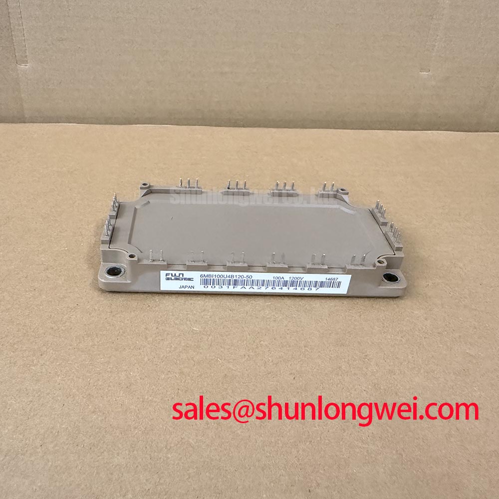
I check terminal screw engagement against the mechanical drawing before tightening a busbar onto the 6MBI100U4B120-50. As a Design Consideration, the relevant stack includes the conductor, washer arrangement, and any approved connecting hardware: a screw that bottoms out can register tightening resistance without producing the intended clamping force. Compare usable thread depth with screw projection through the assembled stack rather than judging engagement from the screw’s overall length.
Seat the conductor without using the terminal screw to pull a misaligned busbar into position. Check that adjacent supports carry the busbar’s weight and that cable movement does not lever the terminal. Washer selection and tightening torque belong to the approved assembly specification; neither follows from the module’s electrical rating. After assembly, inspect for uneven seating and compare connection resistance under consistent measurement conditions. An unusual result warrants checking both the joint and the measurement contacts.
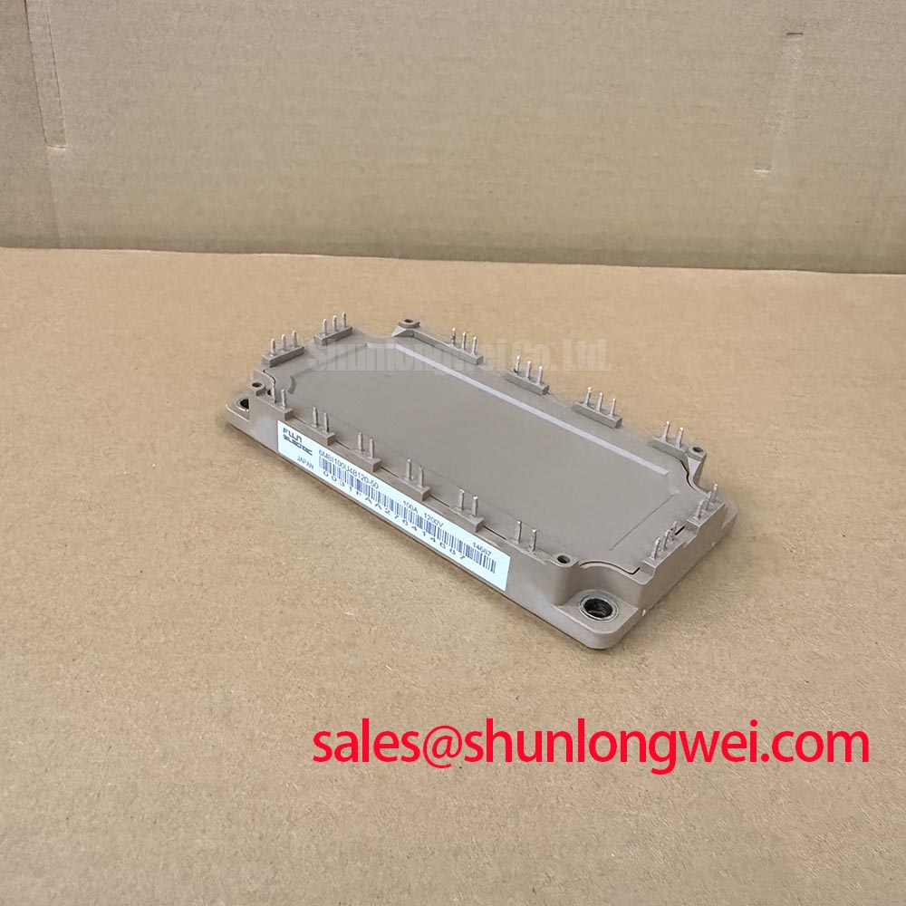
For incoming static inspection, identify collector, emitter, and gate connections from the terminal diagram before applying a meter. With the module disconnected from external circuitry and the gate held at emitter potential using an ESD-safe arrangement, compare diode-mode readings across corresponding antiparallel paths. Record polarity, instrument, and temperature. Differences can justify further investigation, but a handheld reading does not establish rated-current performance or blocking capability.
💡 Bench Tip: Use ESD-safe handling and identical cold-test conditions when comparing gate and diode readings with a known-good reference.
During replacement assessment, the 2MBI600U4N-120-50 is a separate comparison candidate, not an assumed substitute. Compare circuit configuration, terminal allocation, mounting geometry, and driver requirements before considering any change. The 1200 V rating must not be treated as a terminal-to-baseplate insulation test voltage; insulation checks require the specified test connections, voltage, and duration.
6MBI100U4B120-50 Thermal-Electrical Optimization: Optimizing Heatsink Contact Pressure
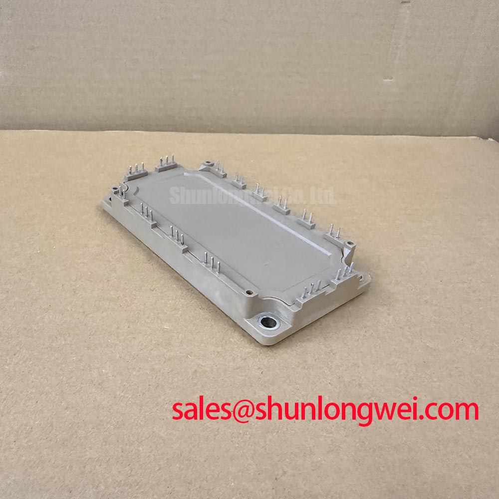
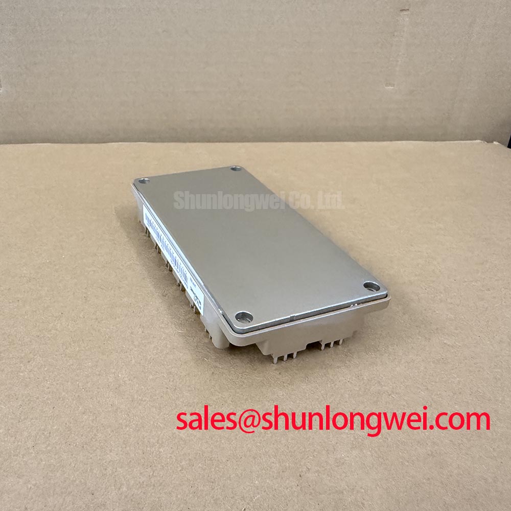
Inspect the heatsink mating surface for burrs, contamination, and uneven contact before applying thermal interface material. As a Design Consideration, select TIM thickness from its application guidance and the permitted mating-surface tolerances, rather than assigning a universal film thickness to this module. Excess material can increase thermal resistance, while incomplete coverage can leave local gaps. Evaluate contact distribution using an assembly-appropriate inspection method.
Bring mounting screws into contact progressively in the specified sequence, then apply the documented final torque with a calibrated tool. Do not compensate for baseplate curvature by increasing tightening force or inserting improvised shims. Check surface flatness and the permitted assembly tolerances instead. Terminal fastening and heatsink fastening are separate mechanical operations, and their requirements should remain separate on the work instruction.
Gate-power integrity deserves attention during thermal evaluation because inadequate drive can increase switching losses. Engineering Recommendation: where the host circuit uses bootstrap high-side power, assess capacitor capacity against gate-charge demand, driver quiescent current, leakage, permitted supply droop, and the longest interval without recharge. Verify recharge opportunities throughout the operating sequence. The capacitor value and supply arrangement are system decisions, not consequences of the 100 A rating.
For compatibility assessment in industrial inverter welders or medium-frequency induction-heating supplies, inspect the complete power schematic rather than assigning a role from a part number. A module such as the 2MBI300U4E-120 elsewhere in the system needs its own switching-stage assessment; it should not automatically be classified as a front-end rectifier. Likewise, any braking chopper and energy-absorbing resistor require separate energy and thermal checks.
6MBI100U4B120-50 Circuit Protection & Reliability: Evaluating Diode Softness and Damping
Capture diode recovery current and the associated collector-emitter transient under controlled switching conditions before adjusting damping. As a Design Consideration, peak reverse-recovery current and recovery abruptness depend on the operating point, including current, temperature, and commutation rate. Static diode-mode comparisons cannot establish those dynamic characteristics, and a softness factor is not a directly adjustable module setting.
Where recovery coincides with ringing, examine the commutation loop and probe arrangement before changing components. An RC snubber or a revised turn-on gate resistor can alter the transient, but selection requires measured overshoot, switching loss, resistor dissipation, and switching timing. Keep connections compact while preserving required electrical clearances. The Evolution of Negative Off-Bias Gate Drive Circuits provides background for evaluating off-state gate control, not a model-specific bias prescription.
Fuji Electric’s High-Speed Discrete IGBT and SiC resources provide broader technology context; their device specifications are not transferable to this module. For parallel operation, assess static and dynamic current sharing separately rather than assuming a positive temperature coefficient guarantees balance. Following an overcurrent event, evaluate the applicable pulse limits and thermal recovery before retesting; continuous current rating alone does not establish an allowable surge or restart interval.