Content last revised on September 12, 2026
Field Diagnostics and Commissioning for Regenerative DC-Bus Surge Dissipation
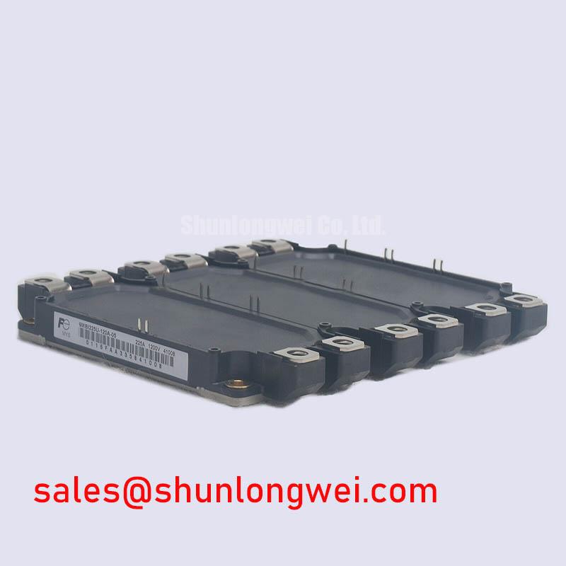
In a low-voltage electric forklift or material-handling traction inverter, regenerative braking can return motor energy to the DC link faster than the battery or front-end converter can absorb it. Engineers evaluating the 6MBI225U-120 should first confirm the braking-chopper topology, the resistor bank, the DC-link voltage waveform, and the protection threshold used by the control system.
The IGBT and ballast resistor must be assessed as one energy-management path. The resistor’s pulse-energy capability, cooling method, duty cycle, and connection inductance are system-level design matters and are not specified by the basic product data supplied here. During commissioning, monitor the DC bus during repeated acceleration and deceleration events, then compare the measured peak against the inverter’s validated voltage limit. A persistent rise in bus voltage may also involve battery acceptance, contactor timing, control-loop delay, resistor degradation, or wiring impedance.
Keep the high-current commutation loop compact and physically separated from encoder, throttle, CAN, and other low-level control wiring. Check terminal surfaces for contamination, inspect busbar joints for discoloration, and retighten connections according to the equipment manufacturer’s documented procedure. Thermal inspection during a controlled braking cycle can help distinguish an overloaded resistor path from a gate-drive or switching problem.
For topology comparison, engineers may review the related 6MBI300U-120 as a separate reference device, but electrical, mechanical, gate-drive, and protection compatibility must be verified independently before any substitution is considered.
Gate-Drive Loop Geometry and Transient Control
Switching behavior depends strongly on the physical gate loop. As a design consideration, route the gate-drive output and its return as a closely coupled pair, while keeping the power-current return path separate from the gate-control reference wherever the documented terminal arrangement permits. This reduces common-emitter coupling and helps prevent control-ground movement from being interpreted as an unintended gate signal.
The gate driver should be evaluated for both sourcing and sinking capability under the actual gate-charge and switching conditions stated in the applicable Fuji Electric documentation. External gate resistance is a tuning component, not an assumed fixed value for this product page. Designers should begin from the validated driver requirements, then adjust damping only after checking turn-on loss, turn-off overshoot, waveform ringing, and fault response with suitable probing techniques.
Use a short, low-inductance measurement connection when observing the gate-to-emitter waveform. A long oscilloscope ground lead can create ringing that is not present at the module terminals. Verify the signal against a known-good drive channel, and inspect whether false protection events occur during high-current commutation rather than assigning them to the IGBT without measurement.
Fuji Electric’s Brake Chopper IGBT Modules information provides useful manufacturer context for braking applications, while the exact ratings and terminal definitions for this model should be checked against the relevant product documentation.
High-Altitude Cosmic-Ray and SEB Risk Assessment
Single-event burnout, terrestrial neutron exposure, and altitude-related derating require application-specific evidence. No model-specific FIT rate, SEB voltage limit, or high-altitude lifetime figure is provided in the supplied product parameters, so a numerical reliability claim would not be appropriate for the 6MBI225U-120.
At installations above approximately 2000 m, altitude can affect cooling performance and may also change the environmental exposure considered in the system reliability assessment. This is a design consideration rather than an automatic failure prediction. The responsible evaluation should combine the actual DC-link operating voltage, switching overshoot, enclosure altitude rating, cooling performance, and any manufacturer qualification data available for the complete drive.
For field troubleshooting, record the DC-bus waveform at the module terminals, inspect the snubber and clamp network, and check for repeated overvoltage events during regeneration. Examine gate timing, desaturation or overcurrent protection behavior, and the physical condition of the module after isolating stored energy. The Field Engineer’s Handbook can support a structured testing and failure-analysis workflow without replacing device-specific qualification data.
Sinusoidal Output Filters, dv/dt Reactors, and Motor-Cable Effects
Long motor leads can behave as transmission structures, creating impedance mismatch and reflected voltage at the motor terminals. A measured terminal spike approaching twice the local travelling-wave voltage is a system phenomenon that must be confirmed with a properly rated differential probe and a measurement point close to the motor, not inferred from the IGBT voltage rating alone.
A dv/dt reactor and a sinusoidal filter serve different purposes. A reactor reduces the steepness of the voltage transition and can limit cable charging current, while a sinusoidal filter seeks to reconstruct a more motor-friendly waveform. Selection depends on carrier frequency, cable length, motor insulation capability, common-mode behavior, filter losses, resonance control, and the drive manufacturer’s permitted configuration.
When integrating the 6MBI225U-120, designers should minimize stray inductance in the switching loop, maintain appropriate clearance and creepage for the actual system voltage, and verify peak voltage margins during switching tests. The filter should be placed and grounded according to its manufacturer’s instructions, with attention to shield termination and the return path for common-mode current.
Maintenance Note: Schedule periodic heatsink cleaning, inspect thermal-interface material for aging, check terminal tightness, and monitor contact temperature while confirming that the cooling airflow remains unobstructed.