Content last revised on October 12, 2026
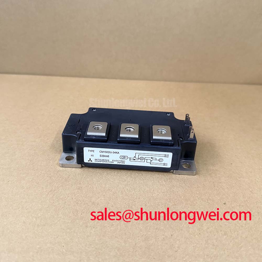
Check the nameplate and isolate the DC link before testing: 6MBP100RA120 | Fuji Electric | IPM Module | 1200 V collector-emitter rating | 100 A at case temperature 25°C continuous collector current | Official Specification.
6MBP100RA120 Thermal-Electrical Optimization: Suppression of 2x V_DC Voltage Doubling at Practical Tuning
I compare the inverter output waveform with the motor-terminal waveform before attributing a long-cable overvoltage to the 6MBP100RA120. As a Design Consideration, impedance mismatch between the cable and motor can reflect a switching edge, producing a motor-terminal peak approaching twice the incident voltage step under suitable conditions. This is a transmission-line effect, not a voltage-doubling feature of the module, and the motor-terminal peak is not automatically the collector-emitter voltage experienced inside the inverter.
Use suitably rated differential measurement equipment and document the probe positions, cable arrangement, DC-link voltage, and operating condition. Compare edge shape, ringing duration, and peak voltage at both ends of the motor lead. A change associated with cable length or routing supports investigation of reflected-wave behavior; it does not independently establish a defective power module. Keep measurement connections compact so probe pickup does not become part of the apparent fault.
The principal electrical boundaries for the Fuji Electric 6MBP100RA120 IPM module are listed below. These are Official Specification values; maximum ratings and typical characteristics serve different purposes during equipment assessment.
| Parameter | Symbol | Official Specification | Assessment context |
|---|---|---|---|
| Collector-emitter voltage | Vces | 1200 V | Device voltage rating, not a prescribed DC-link setting |
| Continuous collector current | Ic | 100 A at Tc 25°C | Specified case-temperature condition applies |
| Pulse collector current | Icp | 200 A | Not a continuous operating-current allowance |
| Collector-emitter saturation voltage | Vce(sat) | 2.3 V typical | Typical characteristic, not a guaranteed value at every load |
| Collector power dissipation | Pc | 650 W per element | Not an assembled inverter cooling-capacity rating |
| Isolation voltage | Viso | 2500 V AC for 1 minute | Specified isolation test, not a continuous working voltage |
| Maximum junction temperature | Tj | 150°C | Junction limit, not an enclosure ambient rating |
As an Engineering Recommendation, evaluate an output choke or dv/dt filter against cable characteristics, motor insulation requirements, load current, and switching behavior. Filter selection belongs to the complete drive system: assess its own heating and its effect on the output waveform before accepting it. Separate output conductors from control wiring, preserve the equipment’s specified electrical clearances, and avoid solving a cable reflection problem by changing module-side components without corresponding measurements.
6MBP100RA120 Thermal-Electrical Optimization: Heatsink Surface Flatness and Thermal Grease Practical Tuning
Inspect the heatsink contact surface for burrs, embedded debris, corrosion, and uneven contact marks before reinstalling the module. Check flatness using the assembly drawing’s acceptance method rather than judging the surface by appearance alone. Assess baseplate profile against the specified mechanical tolerances; do not assume that every visible curvature is damage or that a particular baseplate material has been established.
As a Design Consideration, thermal interface material should fill surface irregularities without creating an unnecessarily thick thermal barrier. Select the material and application method for the actual contact geometry and service conditions. A universal grease thickness is not an installation specification for this part. Keep material away from electrical contact surfaces, and inspect the resulting contact pattern when the approved maintenance procedure permits disassembly.
Use a calibrated tightening tool and the equipment’s specified fastener sequence. Progressive diagonal tightening can help distribute seating load where the mounting arrangement supports it, but final torque must follow the applicable module and assembly instructions. Field Alert: Do not use mounting bolts to force a rocking module flat against the heatsink; correct the contact-surface problem before tightening. Treat the module as its documented package, not as a press-pack assembly requiring improvised disc-spring pressure calibration or double-sided clamping.
The 650 W per-element dissipation rating and 150°C junction limit are Official Specifications, but neither describes the heat removal available in a particular cabinet. As an Engineering Recommendation, assess interface contact, heatsink performance, airflow, and temperature sensing together. Compare thermal behavior at equivalent load and ambient conditions so a cooling change is not confused with a change in electrical duty.
High-side control-power integrity also deserves attention during a thermal repair. If the existing drive circuit uses a bootstrap supply, assess capacitor charge capacity against consumption during the longest high-side interval, including quiescent demand, leakage, and recharge opportunity. Gate charge belongs in that assessment when the relevant driver architecture exposes it; an IPM control input must not automatically be treated as a discrete IGBT gate. Confirm supply droop at the module interface under the actual switching sequence.
Transient Dynamics & Electrical Design: Oscilloscope Waveform Verification: Suppression on 6MBP100RA120
Trace the control-board connections to the IPM interface before changing any resistor described as a gate resistor. The 6MBP100RA120 is an intelligent power module, so discrete-IGBT practices involving accessible turn-on and turn-off gate resistors cannot be transferred without checking the interface schematic. An input resistor may affect signal integrity without controlling the internal gate-current path.
As an Engineering Recommendation, capture control inputs, local driver supply, fault indication, and power-terminal switching behavior on a common timing reference. Check for supply disturbance, unintended input transitions, and recovery behavior around switching events. Use the reference point specified for each signal; a convenient chassis connection can conceal local ground bounce or introduce misleading noise into the measurement.
Where an approved circuit genuinely provides separate turn-on and turn-off adjustment, evaluate changes against switching loss, overshoot, ringing, and protection response. Do not prescribe a resistance or negative gate bias from the voltage rating alone. Negative off-state bias is relevant only to a driver architecture that supports it. For this IPM, control-reference routing and supply integrity should be investigated before attempting changes to internal switching behavior.
A MOV or other suppression component should be evaluated as part of the existing protection network, not added as a universal cure. As a Design Consideration, placement, parasitic inductance, clamp behavior, and repetitive energy exposure determine whether the network intercepts the relevant transient. The technical discussion in Resonant Topologies in Home Appliances offers topology context, but appliance resonant-stage behavior is not a substitute for motor-drive waveform verification.
For replacement assessment, compare 6MBP75VCA120-51 as a separate reference model, not an interchangeable substitute. Consult the datasheet for footprint, terminal assignment, control supply, input logic, fault handling, and thermal characteristics. Electric material-handling equipment and low-voltage forklift traction systems are potential compatibility checks only; the equipment’s original power-stage design must establish suitability rather than the shared manufacturer name or voltage class.
6MBP100RA120 Thermal-Electrical Optimization: Screening Substrate Ceramic DBC Micro-Crack Practical Tuning
Disconnect the module from external power and control circuits before any approved terminal-to-baseplate insulation assessment. Identify the prescribed terminal grouping and test connections first: an insulation tester applied through sensitive control electronics can damage circuits that are unrelated to the insulation path being examined. Remove conductive dust and moisture using the equipment’s approved cleaning procedure, then inspect terminal barriers and surrounding surfaces.
The Official Specification is 2500 V AC for 1 minute. It does not establish a DC insulation-resistance acceptance threshold or authorize repeated field withstand testing. As an Engineering Recommendation, use the manufacturer’s applicable service procedure to determine test voltage, duration, connections, and acceptance criteria. Record environmental conditions and instrument settings so subsequent measurements are comparable.
Insulation resistance alone cannot establish an internal ceramic micro-crack, and the package should not be assigned an unverified substrate construction. Investigate abnormal leakage alongside surface contamination, visible mechanical damage, mounting stress, and the approved electrical test results. Manufacturer-level failure analysis may be needed to distinguish internal damage from an external leakage path. Fuji Electric Global Power Semiconductor Technologies provides manufacturer context for power-semiconductor documentation and application guidance.
As a Design Consideration, inspect both creepage paths along insulating surfaces and clearance through air around terminals, busbars, and nearby metalwork. Conductive deposits can compromise surface conditions even when the original geometry is unchanged. Restore barriers and conductor positioning to the equipment drawings rather than assigning a universal spacing from the module voltage rating.
Before returning the assembly to service, check the specified semiconductor fuse, protection wiring, and fault shutdown path. Fuse I²t coordination requires the relevant device withstand information and prospective fault conditions; the 200 A pulse rating is not a fuse-selection rule or an explosion-containment guarantee. Complete the approved staged restart with protective covers fitted, monitoring leakage indications, fault signals, and temperature behavior before releasing the equipment for normal operation.